| Radio Antenna Engineering is a free introductory textbook on radio antennas and their applications. See the editorial for more information.... |

|
Home  Radio-frequency Transmission Lines Mechanical Construction of Open-wire Transmission Lines Introduction Radio-frequency Transmission Lines Mechanical Construction of Open-wire Transmission Lines Introduction |
||||||||||


|
  |
|||||||||
|
Mechanical Construction of Open-wire Transmission LinesAuthor: Edmund A. Laport
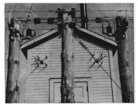
Crossarms and fabricated steel brackets may be used for the proper location of the wires, which may be supported on pin or post insulators or suspended on strain insulators. One or more lines may often be supported on the same pole. When several circuits are to be run on the same supports, two or more poles may be set with a cross frame for supporting the wires. There are regions where wood is scarce or where it deteriorates too rapidly; then poles of tubular steel, structural steel, or concrete are more economical in the long run. Poles and frames may require guying to resist displacement due to horizontal loading of the wires.
The loadings should be precalculated, taking into account the weight, number and tension of the wires under the most extreme conditions of wind and ice to be encountered at the site, stresses at corners and bends in the line, and the soil resistance (mechanical) for the size and depth at which the poles are set into the soil or rock. The design of the crossarm structures must also be based on these considerations. The spans between poles may vary between 25 and 150 feet, and the permissible sags may also vary. Allowance must be made for wind and ice loading and displacement for the range of temperatures of the wires through the year. In some cases it may be desirable to use turn-buckles for adjusting line tension from time to time or to eliminate stretching with age or to employ counterweighting to maintain a constant tension automatically. Certain wire configurations may be susceptible to vibration at certain wind velocities. When this happens, it is desirable to vary the distances of successive spans so that they have different natural periods of vibration. When all the wires of a system are equally stressed, they swing together and maintain mutually normal positions. When small wire spacings are used, wires that are in parallel at the same potential may require the use of metallic spacers and, when of different potentials, spacers of insulating material.
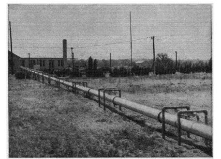
It is more economical to use long spans with rather light wire tensions, and spacers where necessary, than to employ short spans with heavy tensions for the wires. Pole-line construction is an old art, and there are numerous handbooks available giving detailed information from power-line and telephone practices. There is also a wealth of standardized assembly hardware commercially available, and the designer should have at hand several suppliers' catalogues. Radio insulation is much different from that used for power and telephone transmission, and special catalogues for radio insulators are also available. The engineer thus has a wide choice of the details of construction and assembly. The various photographs included in this chapter are intended as examples of what has been done and to serve as suggestions for new installations. They represent a wide variety of individual ideas; yet they are few in comparison with the number of satisfactory methods that one may use. Initial cost will play a prominent role in the detailing of the construction, though the minimum cost will be determined by the amount of power to be transmitted, the frequency, the layout of the station plot in so far as it affects the length of the line, the proximity of the lines to various antennas, the climatic conditions, and the designer's choice of factors of safety.
|
||||||||||
| Home Radio-frequency Transmission Lines Mechanical Construction of Open-wire Transmission Lines Introduction |
|
|||||||||


Last Update: 2011-03-19