| Radio Antenna Engineering is a free introductory textbook on radio antennas and their applications. See the editorial for more information.... |

|
Home  Appendix Appendix IV-B Appendix Appendix IV-B |
|||||||


|
  |
||||||
|
Appendix IV-BAuthor: Edmund A. Laport
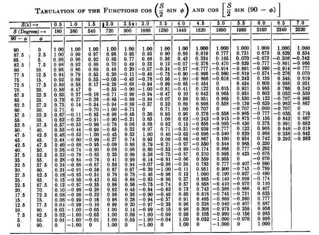
NOTE: When applied to radiation patterns of straight antennas parallel to perfectly reflecting surfaces (such as "ground" or passive reflectors), S represents the electrical spacing between the antenna and its image. Therefore S/2 is the electrical height h of the antenna above ground, or the electrical distance d from a reflecting screen.
These are the patterns in the equatorial plane of two identical parallel nonstaggered radiators with equal currents in antiphase relation. By dividing the column headings for S (degrees) by 2, each column can be read as a vertical pattern for a horizontal antenna over perfectly conducting ground.
These are the patterns in the equatorial plane of two identical parallel nonstaggered radiators with equal cophased currents.
|
|||||||
| Home Appendix Appendix IV-B |
|
||||||


Last Update: 2011-03-20