| Radio Antenna Engineering is a free introductory textbook on radio antennas and their applications. See the editorial for more information.... |

|
Home  Introduction Introduction |
|


|
  |
|
IntroductionAuthor: Edmund A. Laport
Radio communication is accomplished by the transmission and reception of electromagnetic waves that are propagated between two geographical locations by the phenomenon of electromagnetic radiation. A radio-frequency generator, called a radio transmitter, delivers its output power to a transmitting antenna. The transmitting antenna transforms the radio-frequency energy in the antenna circuit to the wave field that is radiated into surrounding space. The waves originating as a disturbance at the transmitting antenna are propagated as detached electromagnetic fields which travel through air with the velocity of light c, where c is 3
This equation is in the rationalized meter-kilogram-second (mks) system of units. Here, µr is the magnetic permeability relative to free space, and εr is the dielectric constant, or inductivity, of the medium relative to free space. εν is the permittivity of free space, which has the value of 8.85 When electromagnetic waves are propagated into the earth (soil), water, metals or any other materials, the velocity may become very low with respect to air owing to the sometimes large values for σ, µ, and ε in the material. A transmitting antenna emits one wave for each period of the exciting potential, or a total number per second equal to the transmitted frequency f. The wavelength λ of the emitted waves is therefore
The wavelength is in the same units as used for the velocity. The size of an antenna is related to the wavelength of emission in some manner; it may have a length of a half wavelength, a quarter wavelength, one-twelfth wavelength, or in some cases one or more wavelengths. The range of wavelengths primarily concerning us in this book is from about 10 meters to perhaps 20,000 meters. One can realize immediately that an antenna one wavelength high at 10 meters is a simple matter, whereas one 20,000 meters high, as a fixed structure, is impractical. For this reason, the use of the longer wavelengths imposes mechanical restrictions on the designer, which in turn introduce difficult electrical conditions. One wavelength being generated per period of the exciting frequency, we can speak of one wavelength as being 360 electrical degrees and use the electrical degree as a unit of physical length which always bears a fixed relationship to the wavelength. In this book antenna dimensions will usually be given in electrical degrees, which is a convenience in engineering because of its direct relation to trigonometric angles used in computations. When we speak of an electrically short antenna, it means one that has a length very small with respect to the wavelength emitted. In accordance with the principle of similitude, the performance of an antenna in free space, infinitely removed from earth, is the same for all antennas of the same electrical size, without regard to their mechanical sizes. Use is made of this principle in making large-scale or small-scale antenna models as a means for obtaining physical data on projected systems. The transmitting antenna comprises the "load" circuit for the radio transmitter, and the power delivered to the antenna is dissipated in heating the conductors, the insulators, and the ground and surrounding parasitic objects and in radiation. The transmitting-antenna resistance therefore is composed of several components which account for these various power losses. The energy "lost" from the antenna circuit because of the radiation of waves into space is of course the useful loss, and that component of antenna resistance which is associated with the radiation of energy is called the "radiation resistance". The efficiency of the antenna system is the ratio of its radiation resistance to its total resistance. In antenna engineering one of the objectives is to make this ratio as large as possible. At the shorter wavelengths efficiencies very near to 1.0 can be achieved conveniently, while for the longer wavelengths the best that can be achieved is much less than this, and sometimes as low as 0.05. Antennas are in general open-circuit systems of electrical conductors projecting into the space in which the radio waves are propagated. These conductors are connected to the transmitting and receiving apparatus, which are closed-circuit devices. The charges moving in the transmitting antenna cause disturbances in the surrounding space which generate the waves propagated outward into space, with attenuation and variations which increase with the distance from the transmitting antenna. The passing wave field induces the movement of charges in the conductors of the receiving antenna, which causes currents and potentials to be built up in various parts of the system and combined at the point where the radio receiver is connected to the antenna system. The receiver input power is amplified, detected, and delivered to an electromechanical transducer of a type which will be actuated by the signal received and will disclose the intelligence which it contains.
In a book of this nature we shall take for granted the dynamic relationships established in the electromagnetic theory between electric charge, electric flux, electric field strength, electric current, magnetic flux, and magnetic field strength and shall apply these relations in the manner of the engineer. The reader who wishes to have a full understanding of the theoretical foundations of electromagnetic theory and electromagnetic radiation may consult many excellent modern treatises, such as Stratton
Consider further that the middle of this doublet is the center of a system of polar coordinates with the axis of the conductor along the 0 axis of the coordinate system. The angle 6 is measured from this axis and may be called a "colatitude angle." The longitude angle φ is measured from some arbitrary reference direction in the equatorial plane. The distance from the origin of coordinates will be designated by r. When the electric field is measured at a point in space several wavelengths from the doublet and this point has the coordinates θ, φ, and r,
This equation expresses the absolute magnitude and relative phase of the field at all values of θ and r; but, owing to axial symmetry, the field is independent of φ. If we consider only the factor giving the magnitude of the field, it is seen to be directly proportional .to the current and to the length of the doublet; that it is proportional to the sine of θ and is therefore zero in the direction of the doublet axis and maximum in the equatorial plane where θ = 90 degrees; and that it is inversely proportional to the distance and to the wavelength when r, l, and λ are measured in meters. If instead we change both the length of the doublet and the wavelength to electrical degrees, we shall obtain the same result. As a valuable example, let us assume that the current is unity, l is 1 electrical degree, λ is 360 degrees, and r is 1,610 meters (1 mile). When these values are substituted in this equation, we compute a value of 325 This field equation is for the radiation field only. Near the doublet, there are two additional terms for the total field (which are omitted from our equation) that are described as the static field and the induction field, which vary inversely as r3 and r2, respectively, and which therefore quickly fall to negligible values as the distance increases. The induction field has decreased to 1 percent of the value of the radiation field at a distance of 16 wavelengths. The values of E plotted in all directions, but at constant distance from the center of the system, describe the space characteristic, or radiation pattern. The pattern for a free-space doublet is the fundamental unit used to derive the radiation pattern for antennas having various spatial distributions of currents. Each element of length of a wire in an antenna system contributes as a doublet to the over-all field for the antenna system made up of the contributions from all the current-carrying elements. The pattern for an antenna is understood to be determined at a distance so large with respect to the largest dimension of the antenna that the rays from each doublet portion are essentially parallel and the effect of the different values of r from each doublet portion to the distant point are essentially equal. This is the so-called "Fraunhofer region," where the shape of the pattern is independent of r. The radiation pattern then is the integration of all the elements of radiation contributed by all the currents of the system, taking into account their relative magnitudes, initial phase differences, and the phase differences introduced by their propagation over different path lengths. The basic relation for the radiation field from an elementary doublet is
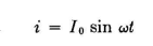
This gives its fundamental pattern shape and relative magnitude. The pattern for any antenna system is the integration of the contributions of all its elementary doublets. These basic facts can be brought down to a very useful summary if we consider a doublet that has an electrical length of 1 degree, with a uniform current of 1 ampere flowing throughout its length. The field strength produced by a moment of 1 degree-ampere in free space has already been shown to be 325 microvolts per meter at 1 mile from the doublet in the direction normal to the doublet axis. So long as all the currents in a system of coaxial doublets are cophased, each degree-ampere contributes 325 microvolts per meter in this direction. When reversed currents are present, the antenna field will be the algebraic sum of the fields produced by the positive and negative degree-amperes. When a doublet is located over a perfectly conducting infinite flat plane and oriented either horizontally or vertically, the maximum field strength produced by the combined direct and reflected wave fields is twice that from the doublet in free space. Therefore, over perfectly conducting flat earth, each degree-ampere contributes 650 microvolts per meter at 1 mile to the total field in the maximum direction. When the doublet is horizontal, the maximum field will be at some angle to ground determined by its electrical height; and if the height be large electrically, there will be several such maximums. Again, the field maximums occur normal to the doublet. A straight half-wavelength dipole in free space having sinusoidal current that is in time phase throughout its length but distributed sinus-oidally in magnitude as a function of the distance in electrical degrees from either end of the dipole has an integrated radiation field which is completely expressed by the relation where I0 is the instantaneous peak value of the current at the center of the dipole.
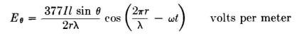
This equation has the factors indicated as A, B, and C which have the following physical meanings: A. This is the amplitude factor which shows that the field strength is proportional to the current varying sinusoidally in time, with a peak instantaneous value of I0 at the center of the dipole, and that the field strength is inversely proportional to the distance r from the dipole. The constant 60 sets the absolute value in volts per meter at unit distance, and is 377/2 π, very nearly, where 377 (ohms) is the intrinsic impedance of free space to a plane wave. B. This factor results from integrating the distant fields from the distribution of doublets with their relative currents along the dipole (sinusoidal current distribution) and is the radiation pattern for an idealized half-wave dipole as a function of θ. This factor is often used alone in engineering studies where only the shape of the radiation pattern is of interest. C. This factor states that the phase of the electric field is leading that of the field at the source at any instant by 360 degrees per wavelength, measured along the propagation path. This is because of the finite propagation for a wavefront to arrive at the distance r, during which time the phase of the source has fallen behind this wavefront by 360r/λ electrical degrees. In using half-wavelength (or half-wave) dipoles as elements in more extensive antenna systems, the radiation patterns may be computed on a relative rms basis using the relation where I is the rms current at the center of the dipole and the electric force Fθ is now in arbitrary relative units.
If instead of using the colati-tude angle θ we wish to measure θ1 as a latitude angle from the equatorial plane of the system, as we do frequently, we take θi as the complement of θ and by substitution, to obtain
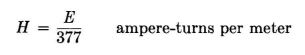
A half-wave dipole has a moment of 114.5 degree-amperes per ampere at its center. This produces a field strength of 37.3 millivolts per meter at 1 mile from the antenna for each ampere of antenna current. Over perfectly conducting ground, the image radiation (waves reflected from the ground) contribute an equal amount to the resultant field, producing a field strength of 74.6 millivolts per meter at 1 mile per ampere at those angles where the direct and reflected waves add in phase. From now on, with this information, we can use the half-wave dipole as the fundamental element in an antenna array composed of half-wave dipoles, integrate the contributions of each such dipole to the total field of the array, and thereby compute the radiation pattern for the array. At this point one can summarize the basic physical facts of doublets and dipoles in easily remembered form as follows: The free-space radiation pattern for a very short doublet is the solid of revolution generated by a circle tangent to the doublet. The free-space radiation pattern for a half-wave dipole is the solid of revolution generated by an oval tangent to the dipole with its major axis normal to the dipole. The minor axis of the tangent oval is 90 percent of the major axis. These facts will be used extensively throughout the book in dealing with radiation patterns. However, because practical antennas must usually be built close to the earth, the symbols for the reference angles will be changed to a for the elevation angle from the horizon and ß for the azimuth angle from the normal to a dipole, or clockwise from true north, or some other reference in systems using vertical radiators. The magnetic force H of a plane electromagnetic wave can be derived from the electric force, or electric field strength E, through the relation in air. In this relation E is in volts per meter, and 377 is a constant known as the "intrinsic impedance" η of free space in ohms.
It is obtained from the relation where μν is the permeability of free space, which is 4 π· 10-7 henry per meter.
Whereas the intrinsic impedance of free space for a plane electromagnetic wave is the ratio of E and H, the vector product of E and H gives the Poynting vector P, or the power flow in watts per square meter in the direction of propagation or in the plane of the equiphase surface of the wave. Both E and H are vector quantities in that they both have direction and magnitude at any point in space. They are perpendicular to each other and to the direction of propagation. Through these simple equations, which are consequences of using the meter-kilogram-second (mks) system of units, plane-wave relations become analogous to Ohm's and Joule's laws for circuits. Therefore we can go on to other obvious relations such as
Most field-strength meters are calibrated in terms of volts per meter, millivolts per meter, or microvolts per meter. From a measurement of field strength one can determine directly the power flow in watts per square meter. If the effective pickup area (or the effective aperture) of a receiving antenna is known, the total power delivered at the receiver input from the passing wave field becomes known. It is assumed in this statement that the wave field is arriving from the direction of maximum response of the receiving antenna. The classical original method of computing the radiation resistance of an antenna was to compute its radiation pattern at great distance in terms of field strength and square the field strengths at all points on an enclosing hemisphere (in the case of an antenna located near the ground). The radiation pattern then is in terms of power flowing outward through the hemisphere, and the integration of power flow over the surface of the enclosing hemisphere gives the total radiated power from the antenna. The radiation resistance then is the ratio of the radiated power and the square of the antenna current. Since the antenna current is usually a function of position in the antenna, the value of radiation resistance will depend upon what point in the system it is referred to - usually the point where the antenna is fed by the transmitter or at a point of maximum current. Radio transmission sometimes is to specific targets, as in point-to-point communication, and sometimes to a multiplicity of targets of general geographic distribution, as in broadcasting. The radiation of electromagnetic waves to specific fixed targets permits the use of antennas that are directive and concentrate the radiant energy like a searchlight beam in the desired direction. Directive antennas make use of the principles of wave interference to combine the fields from a multiplicity of radiators synchronously excited so that they add their effects in the desired direction and cancel partly or wholly in other directions. . The suppression of radiation in unwanted directions causes reinforcement of the energy in the wanted direction, and this increase in the intensity of the wave field is equivalent to increasing the effective radiated power in this direction. The increase in field due to directivity as compared with a nondirective antenna gives rise to the antenna characteristic known as "gain." In reality there is no known type of antenna that is not directive in some way, although the "isotropic" antenna having equal radiated field strength in all directions (spherical radiation, like the radiation of light from an isolated point source of illumination) is taken as a theoretical standard of reference. Every kind of practical radio antenna is directional to some extent because of the doublet field distribution for a straight conductor and also because of interference between radiations from each infinitesimal element of its geometric configuration and interference between the waves radiated directly into space with those reflected from the earth and other objects against which the waves inevitably impinge. Therefore even antennas that are regarded as omnidirectional are so only in a certain sense - usually in the sense that the antenna is nondirective geographically in the earth plane. The receiving antenna has the function of extracting the maximum power from a passing wave field and at the same time intercepting a minimum of other radiations inevitably present owing to unwanted signals from other stations that cause interference and to natural or man-made electrical noise. The most important factor at the radio receiver is the signal-to-noise ratio, in this case considering interfering signals from unwanted stations as a component of the total noise present. Radio communication is impractical when signal-to-noise ratios fall below certain values, the values depending upon the kind of communication, whether telegraph, telephone, facsimile, television, etc. (see Appendix VII). The minimum value of signal-to-noise ratio below which the transmission is impaired to the point of interrupting communication may be due to weak incoming signals or to high noise pickup. When the ambient noise pickup is very small, the limiting noise may be that due to thermal agitation in the antenna conductors and in the receiver input circuits. The propagation of radio waves over a given path between transmitting antenna and receiving antenna is beyond human control; in this respect, radio communication differs from other forms of electrical communication where the propagation medium is specifically designed and built for the purpose. In each chapter of the book dealing with the three different classes of antenna design, a resume" is given of the characteristics of propagation, leading up to the antenna-design techniques best adapted to the special propagation conditions existing in the relevant portions of the radio spectrum. In free space devoid of all substance, including air or gases, an electromagnetic wave is propagated without any dissipation of its energy. The inverse relationship between field strength and distance is due to the expansion of the wave in three dimensions and the distribution of radiant energy over a larger and larger volume of space, so that the power flow follows the inverse-squares law with respect to distance. In a macroscopic sense, therefore, radio waves are spherical waves. However, in view of the relatively small portion of this spherical wave utilizable at a typical distant radio receiving position, the equiphase wavefront in this small region may be considered in a microscopic sense as a plane wave. The laws of reflection and refraction for plane waves are easily formulated and applied practically. A plane wave impinging upon the plane interface between empty space and some other medium of different permeability and permittivity splits the wave into two components, one reflected from the interface and the other refracted into the second medium, where it is propagated at different velocity and in a different direction, The exact nature of this phenomenon depends upon the orientation of the electric vector of the wave with respect to the interface - whether parallel to it, normal to it, or oblique, with both parallel and normal components. It also depends upon the intrinsic impedance of the second medium, whether it is a perfect conductor, a perfect dielectric, or a complex (imperfect) dielectric having both induc-tivity and conductivity. The surface of the earth, which we often call simply "ground," is always a complex dielectric. This fact complicates the quantitative details of wave reflection from the ground to such an extent that in ordinary engineering usage little attempt is made to deal with the effect quantitatively. For one reason, the empirical constants of the ground over the areas and the depths that are involved in any particular problem can be ascertained only approximately by the best available techniques. The most exact values, of course, are for water, where the measurement of a small sample can be made in the laboratory. Soil is not so homogeneous, and furthermore its constants can vary greatly with moisture gradients and with weather and also with frequency owing to the different depths of penetration of earth currents. It is general practice to postulate antenna performance on an idealized basis, considering the antenna itself to be lossless and the ground to be perfectly conducting. With this as a standard, the compromises due to surrounding empirical effects which cause losses and modify the radiation pattern can be taken into account separately to the extent that the problem warrants. The empirical factors are omitted entirely in many ordinary engineering problems, with satisfactory practical results. The empirical characteristics of the ground have an important effect on the technique of designing ground systems to collect ground currents in the most efficient way. One technique consists virtually in "metal plating" the ground so that the ground currents associated with the antenna flow almost wholly in buried wires, with very small current densities in the ground itself. The other basic technique is to use ground collector electrodes or capacitance areas in such a way that the current densities in the ground are as uniformly diffused as possible throughout the volume of ground in which there are appreciable currents associated with the antenna circuit.
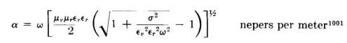
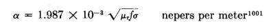
In homogeneous imperfect dielectrics the attenuation of a plane electromagnetic wave
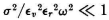
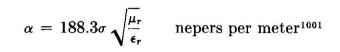
All units are in the meter-kilogram-second (mks) system. When σ2/εv2εr2ω2 >> 1, conduction currents predominate over displacement currents and the equation for attenuation reduces to
Appendix II gives the so-called "skin depth" of ground currents (depth at which the wave attenuation is 1 neper or 8.686 . . . decibels) for this case. [For conversion from meter-kilogram-second (mks) to electromagnetic centimeter-gram-second (cgs) units, σmks = 1011 σcgs.] When
For geologic materials μr is 1, usually.
|
|
| Home Introduction |
|
 108 meters per second.1 In other mediums, the velocity of propagation of plane electromagnetic waves


Last Update: 2011-03-19