| Transistor Basics is a free introductory textbook on transistors and their basic applications. See the editorial for more information.... |

|

Home  Transistor Amplifiers Transistor Amplifiers  Class A Amplifiers Class A Amplifiers  Efficiency Stabilization Efficiency Stabilization |
||


|
||
|
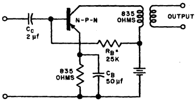
Efficiency StabilizationAuthor: Leonard Krugman Figure 5-8 represents a typical Class A transistor amplifier using d-c operating biases as described in the preceding paragraphs. The stabilizing resistor in the emitter circuit is made equal to the load impedance in this case. In general, this amount of stability control is needed only in mass production applications if transistors having a wide tolerance range are to be used. Actually, the reproducibility of transistor characteristics has improved rapidly during the past few years. There is no reason why this trend should not continue, and eventually permit the attainment of amplifier efficiency values very close to the theoretical maximum. In most circuits, between 5 and 10% of the collector d-c power (EcIc)is satisfactory for normal stabilization. In the circuit shown in Fig. 5-8, for example, a resistance of 100 ohms between the emitter and ground would be sufficient.
Fig. 5-8. Class A amplifier.
|
||
Home  Transistor Amplifiers Transistor Amplifiers  Class A Amplifiers Class A Amplifiers  Efficiency Stabilization Efficiency Stabilization |
||
Last Update: 2010-11-17


