| Transistor Basics is a free introductory textbook on transistors and their basic applications. See the editorial for more information.... |

|

Home  Transistor Oscillators Transistor Oscillators  Negative-Resistance Oscillators Negative-Resistance Oscillators  Oscillator Stabilization Oscillator Stabilization |
||


|
||
|
Oscillator StabilizationAuthor: Leonard Krugman The generated signal of the sine-wave oscillator becomes badly distorted when the dynamic operating range of the circuit exceeds the negative-resistance region; excessive and uncontrolled distortion causes frequency instability. Obviously, the reduction of the harmonic content to a minimum is particularly important in those applications that require a stable and pure sine wave. But even in those cases where a high harmonic content is desirable, steps are necessary to keep the harmonic content of the signal constant to insure frequency stability of the oscillator.
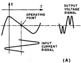
Fig. 6-11. Effect of a-c load on harmonic content: (A) idealized a-c resonant load; (B) A-c toad slightly less than negative resistance of characteristic.
The operating point must be stabilized in the center of the negative-resistance region in order to avoid distortion from unequal positive and negative signal amplitudes. When the external resistances are fixed, the main causes of operating point shifts are changes in the bias supplies. An effective method of stabilization is the use of one supply battery for both the emitter and collector bias. This assures that the ratio Increasing the resonant impedance of a series resonant arm is accomplished by selecting a higher resistance inductor, or by increasing the value of the series resistor in the emitter or collector lead. Decreasing the resonant impedance of the base controlled tank circuit is not as simple. A reduction of the tank Q will, of course, decrease the resonant impedance, but a low Q tank tends to promote frequency instability. A more satisfactory method of decreasing the impedance is to tap the base lead at some point in the tank coil. This permits the retention of a high Q tank, and, at the same time, reduces the effective impedance connected in the base lead. In addition, this connection helps to reduce the effects of internal transistor reactances on the operating frequency. These internal reactances, primarily caused by junction capacitances, are particularly troublesome because their values do not remain constant with changes in temperature and changes in operating currents and voltages. However, loose coupling between the tank and the base circuit minimizes the effect of internal transistor reactance. While this reduces the available power of the oscillator, the sacrifice of power for stable operation is generally justified. The level of the signal can always be increased by a stage or two of amplification. Amplitude stability in negative-resistance oscillators is generally accomplished by incorporating some form of automatic bias control in the circuit. Sometimes the required amount of degenerative feedback is obtained through a non-linear resistor, placed in either the collector or emitter circuit. In this case, the main problem involves finding a non-linear element that is sensitive to the small current changes involved. Amplitude stability may also be obtained by a loosely coupled tank in the base-controlled oscillator, since it automatically decreases positive feedback at frequencies off resonance.
|
||
Home  Transistor Oscillators Transistor Oscillators  Negative-Resistance Oscillators Negative-Resistance Oscillators  Oscillator Stabilization Oscillator Stabilization |
||
Last Update: 2010-11-17


 will remain constant in spite of variation in the battery potential.