| Electrical Communication is a free textbook on the basics of communication technology. See the editorial for more information.... |

|
Home  Electrical Fundamentals of Communication Parallel (Phase) Resonance Electrical Fundamentals of Communication Parallel (Phase) Resonance |
|||||


|
  |
||||
Parallel (Phase) ResonanceParallel resonance is defined1 as "the steady-state condition which exists in a circuit comprising inductance and capacitance connected in parallel, when the current entering the circuit from the supply line is in phase with the voltage across the circuit." From this definition the input impedance of the circuit at resonance is equivalent to pure resistance. This is often called parallel resonance. The term antiresonance is sometimes used to designate parallel resonance. The term current resonance is also used, a term correctly applicable only if the effective resistance is negligible.
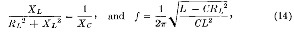
Resonance (phase) occurs in a parallel circuit composed of an inductor and capacitor when the inductive susceptance BL = XL/ZL2 equals the capacitive susceptance Bc = XC/ZC2, and the reactive component of the current through the inductor equals the reactive component of the current through the capacitor. For the practical case of a parallel circuit composed of an inductor having effective resistance R and a capacitor having negligible loss, the inductive susceptance is BL = XL/(RL2 + XL2) and the capacitive susceptance is BC = 1/XC. The resonant frequency is
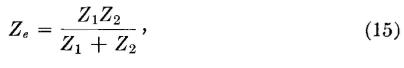
where / is the (phase) resonant frequency in cycles per second when L is the inductance in henrys, C is the capacitance in farads, and RL is the effective resistance of the inductor in ohms. For many parallel circuits equation 13 is satisfactory. The way the input impedance of a parallel circuit varies with frequency is shown in Fig. 10. Note that the input impedance is high at resonance. The voltage across a parallel circuit at resonance is E = IRe, where Re is the equivalent parallel resistance. From the familiar equation for equivalent impedance of any parallel circuit,
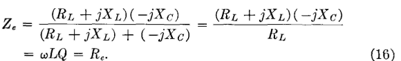
the equivalent parallel impedance of the inductor and capacitor previously considered is approximately
This last expression applies at radio frequencies where RL is small compared with XL, where RL is neglected in the numerator, where XL = XC, and where Q = ωL/RL. The voltage at resonance across the parallel inductor and capacitor is E = IZe = IωLQ. Because the input impedance is greatest at resonance, the voltage across a tuned parallel circuit to which the current input I is constant also is greatest at resonance, and this property is made use of in practice to obtain a high signal voltage. At resonance the current through the inductor and capacitor are IL = E/ZL and Ic = E/XCj respectively, and may be quite large at resonance; this property also is utilized in practice.
|
|||||
| Home Electrical Fundamentals of Communication Parallel (Phase) Resonance |
|
||||


Last Update: 2011-05-30