| Electrical Communication is a free textbook on the basics of communication technology. See the editorial for more information.... |

|
Home  Electrical Fundamentals of Communication Direct-Current Bridges Electrical Fundamentals of Communication Direct-Current Bridges |
|||||||


|
  |
||||||
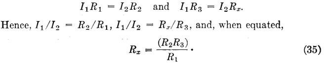
Direct-Current BridgesMeasurements of direct-current resistance often are made with the Wheatstone bridge shown in Fig. 16. In operating, R1 and R2 are usually set on some convenient ratio, and resistor R3 is then adjusted until the galvanometer does not deflect.
Since the galvanometer does not deflect, the points across which it is connected are at the same potential. Then,
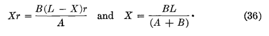
This bridge is used to find faults such as short circuits, crosses, or grounds on communication circuits. One method is the Murray loop shown in Fig. 17. The lower wire on which the accidental ground exists is connected at the distant end to a clear wire. The bridge is then balanced. Suppose that the two wires have the same resistance r per foot and that the total loop length L is known. Then, if A, B, Y, and X correspond to R1, R2, R3, and Rx of Fig. 16 and equation 35, the distance X to the fault is
If the two wires have different resistances r1 and r2 per foot because a wire of the same size was not available for connection with the faulty wire, Rx = Xr2, and
When these substitutions are made in equation 35, the distance is
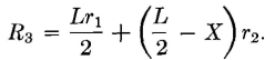
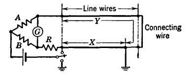
Another method of finding faults is the Varley loop of Fig. 18. This arrangement offers the possibility of throwing the switch up and measuring the loop resistance. Suppose that in this figure the two wires have the same resistance r per foot and that the total loop resistance RL has been measured. Then, when the switch is thrown down and the loop balanced, R3 of equation 35 is RL-Xr, and Rx is R + Xr. Hence, from equation 35,
and the distance X to the fault is
In this equation, RL is equal to the loop length L times the resistance per foot r. If the wires do not have the same resistance per foot, it is easily shown that equation 38 can be used to find the distance to the fault if r is the resistance per foot of the grounded wire.
|
|||||||
| Home Electrical Fundamentals of Communication Direct-Current Bridges |
|
||||||


Last Update: 2011-05-30