| Electrical Communication is a free textbook on the basics of communication technology. See the editorial for more information.... |

|
Home  Electrical Fundamentals of Communication Impedance Transformations Electrical Fundamentals of Communication Impedance Transformations |
|||||||


|
  |
||||||
Impedance TransformationsThe two preceding sections considered methods of changing the magnitude (but not the angle) of a load impedance. Transformers are often used for this purpose. Such methods are used in audio-frequency circuits where the band width is great compared to the magnitude of the center frequency. In contrast, the band width occupied by the radio channel is such a small per cent of the carrier frequency that in much radio design work it can be assumed that a single frequency is to be transmitted. Hence, it becomes possible to change angles as well as magnitudes in impedance matching. Such transformations will be treated in this section. The discussion applies to a single frequency, or to a relatively narrow band of frequencies.
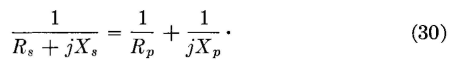
Equivalent Series and Parallel Circuits. A method of making impedance transformations is based on equivalent circuits.15 Two circuits are equivalent if they draw identical currents when they have the same voltage impressed on them. The current taken by the series circuit of Fig. 13 is Is = E/(Rs + jXs), and by the parallel circuit Ip = E/Rp + E/(jXp). If the circuits are equivalent, these two expressions can be equated:
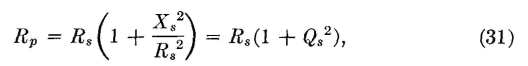
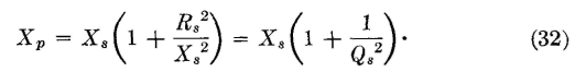
For equivalence, the two in-phase components of current must be equal, and the two out-of-phase components must be equal. Thus in equation 30 the real terms must be equated separately, and the reactive terms must be equated separately. When this is done,
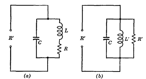
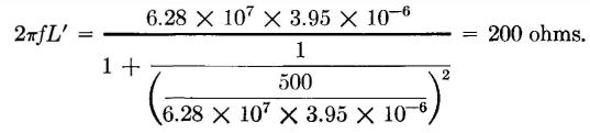
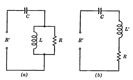
Increasing an Impedance. Impedance transforming circuits are used extensively in radio. Usually the load to be matched contains both resistance and reactance. This reactance is often neutralized (and the phase angle of the load changed) by connecting an equal and opposite reactance in series. If this is done, then there remains only resistance to be transformed into a new value. A method of increasing a resistance will now be considered. The circuit of Fig. 14 (a) can be used to increase a resistance to a larger value. The resistance R may be a resistor or a circuit actually inserted in series with the inductor L, or it may be resistance reflected in series with the coil in accordance with coupled-circuit theory. Assume that R must appear as a larger value R' at the points indicated. The principle involved is to transform R to the desired value R' by connecting R in series with some inductor L. The equivalent inductance L' then is neutralized with capacitor C, leaving only the transformed value of R' effective between the terminals. As an illustration, suppose that it is desired to transform 100 ohms resistance to 500 ohms resistance at 5.0 megacycles. Using equation 31
and L = 6.35 x 10⁻⁶ henry. This is the value of inductance to insert in series with the resistance to be transformed. It is now necessary to find what the reactance of L' of Fig. 14(6) will appear to be. This can be found from equation 32, and is
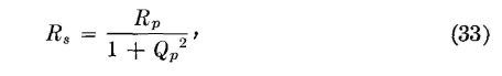
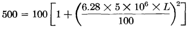
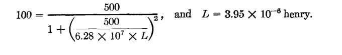
Decreasing an Impedance, As an illustration, suppose that it is desired to transform a 500-ohm resistance to a 100-ohm resistance at a frequency of 10.0 megacycles. For this purpose, the circuit of Fig. 15(a) can be used. The method is to find the value of the inductor L that must be placed in parallel with the 500 ohms so that it will appear as 100 ohms at R'. Then it is necessary to find the equivalent series reactance of L and R so that this reactance can be neutralized with capacitor C, leaving only resistance R' between the input terminals. Using equation 33
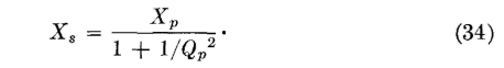
This is the value of the coil L to be connected in parallel with R to cause R' to equal 100 ohms. The equivalent series reactance of the L and R combination of Fig. 15(a) can be found by equation 34, and is
|
|||||||
| Home Electrical Fundamentals of Communication Impedance Transformations |
|
||||||


Last Update: 2011-05-14