| Electrical Communication is a free textbook on the basics of communication technology. See the editorial for more information.... |

|
Home  Electric Networks Filters Band-Pass Filter Electric Networks Filters Band-Pass Filter |
|||||||||||


|
  |
||||||||||
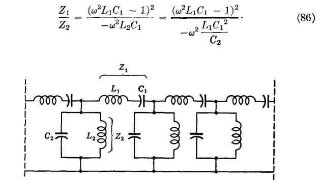
Band-Pass FilterThis filter is designed to pass a given band of frequencies, and to attenuate all other frequencies. A band-pass filter of the constant-k type is shown in Fig. 37. The arm Z1 is resonant for some frequency fc, and Z2 is anti-resonant at this same value. At the resonant frequency fr, Z1 offers zero impedance and Z2 offers an infinite impedance. Although more generalized structures are possible,4,5 only the simple "confluent" band-pass filter passing only one band will be considered. In this structure, L1C1 = L2C2.
For the filter of Fig. 37,
and
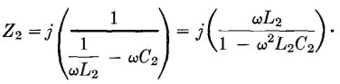
The ratio Z1/Z2 (when L1C1 = L2C2, and L2 = L1C1/C2 are substituted) is
A network of this general type will pass frequencies between Z1/Z2 = -4 and Z1/Z2 = 0. Accordingly, equation 86 becomes
As equation 87 indicates, an upper and a lower cutoff frequency are obtained; that is, and
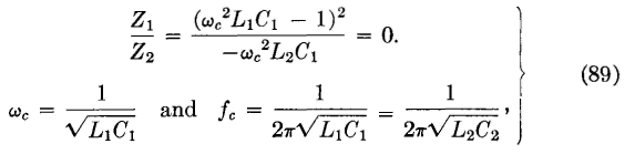
These cutoff points were found by Z1/Z2 = -4. When the ratio is equated to zero, Then,
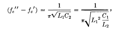
since L1C1 = L2C2. This is not a true cutoff frequency,4 but lies at the middle of the band passed. It is the frequency for which the series arm is resonant and the shunt arm antiresonant as previously considered. In a generalized filter there are two bands passed; but with L1C1 = L2C2 these two bands "flow together" and the filter is of the simple confluent type. If the two expressions of equation 88 are subtracted,
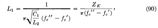
since L1C1 = L2C2. Then,
where ZK = sqrt(L2/C1) = sqrt(L1/C2) and is the iterative impedance taken at the resonant frequency. By making similar substitutions,
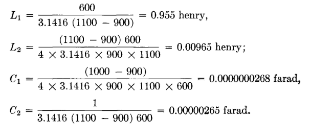
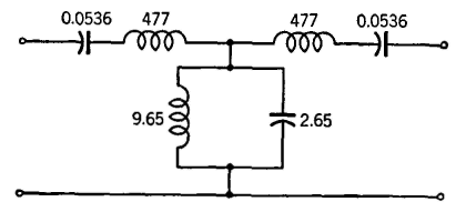
As an illustration of the design of a simple confluent constant-k band-pass filter, assume that it is desired to construct a filter such that ZK = 600 ohms, fc' = 900 cycles, and fc" = 1100 cycles. Then,
The values here computed are for the entire series and parallel arms of Fig. 37. If a T section is desired, it should be constructed as indicated in Fig. 38. Also, the values for a π section may be readily determined.
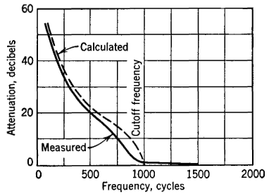
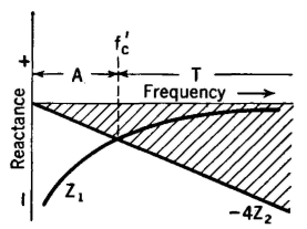
The attenuation curve for a band-pass filter of this type would be approximately as shown in Fig. 39. The pass bands can also be computed by reactance sketches4,5 as in Fig. 40. This sketch is not for the simple confluent type just considered. It will therefore be noted that -4Z2 values determined by the parallel or antiresonant circuit do not pass through infinity at the same point that the Z1 curve determined by the series elements passes through zero. The two transmission bands T and T' are accordingly not confluent and, as the diagram indicates, exist separately. This figure represents a double band-pass filter.
|
|||||||||||
| Home Electric Networks Filters Band-Pass Filter |
|
||||||||||


Last Update: 2011-06-05