| Electrical Communication is a free textbook on the basics of communication technology. See the editorial for more information.... |

|
Home  Transmission Lines Current Distribution on an Open-Circuited Lossless Line Transmission Lines Current Distribution on an Open-Circuited Lossless Line |
|||


|
  |
||
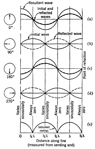
Current Distribution on an Open-Circuited Lossless LineAn electromagnetic wave consists of both electric field and magnetic field components. Thus, in studying wave-reflection phenomena, current distribution, as well as voltage distribution, must be investigated, and Fig. 7 will be used.
The impressed voltage will, of course, force a current into the line. The initial current component of the electromagnetic wave will travel down the line as indicated in Fig. 7(a) Because the line is open circuited, the current at the distant end must be zero. For this to be possible it is necessary that a 180° phase shift of the magnetic field and current component of the electromagnetic wave occur at the open-circuited end of the line. Then, the reflected component will cancel the oncoming initial component, and the resultant magnetic field and the current will be zero. If the relations between the initial and the reflected components are studied for other input phase positions, Figs. 7(b), (c), and (d) result. If thermomilliammeters are inserted at various points along the line, the effective value of the current readings will plot as shown in Fig. 7(e). This curve is called a current standing wave.
|
|||
| Home Transmission Lines Current Distribution on an Open-Circuited Lossless Line |
|
||
Last Update: 2011-05-30