| Electrical Communication is a free textbook on the basics of communication technology. See the editorial for more information.... |

|
Home  Electronic Applications in Communication Amplifiers Radio-Frequency Power Amplifiers Electronic Applications in Communication Amplifiers Radio-Frequency Power Amplifiers |
|||||||||||||||||||||||||||||||||||||||||||||||||||||||||||||||||||||||||||||||||||||||||||||||||||||||||||||||||||||||||||||||||||||||||||||||||||||||


|
  |
||||||||||||||||||||||||||||||||||||||||||||||||||||||||||||||||||||||||||||||||||||||||||||||||||||||||||||||||||||||||||||||||||||||||||||||||||||||
Radio-Frequency Power AmplifiersThe basic circuit of both class B and class C radio-frequency power amplifiers is shown in Fig. 26. The grid is highly biased, often from 2 to 3 times cutoff for class C operation. The grid usually is driven positive so that grid current flows for the angle of flow θg of Fig. 27. Plate current will flow for the angle of flow θp. (Sometimes one-half these angles is taken as the angle of flow.)
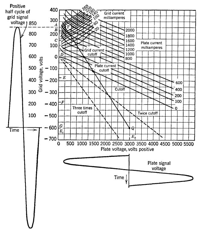
The plate current is badly distorted and is given by a series similar to equation 1. The parallel circuit (sometimes called a tank circuit) in series with the plate is tuned to the fundamental signal frequency, and hence this is passed to the output, and the harmonics are suppressed. The phase relations are about as shown in Fig. 18. Constant-current curves such as those in Fig. 28 are used for calculating the performance of power triodes in class B or class C. The problem is usually to ascertain the operating conditions for maximum
power output and efficiency and is a cut-and-try process. One method of solution, using a class C amplifier as an illustration, will now be summarized from reference 12. The quiescent (no signal) Q point is selected first. In Fig. 28 this is at 2.5 times cutoff, and, if the plate voltage is to be +3000 volts, the corresponding grid-bias voltage is -600 volts. The tip point or T point, which is the peak positive grid voltage to which the grid is driven and the minimum voltage to which the plate falls, is selected next. In Fig. 28 these values are each +250 volts. This gives a grid-voltage swing of 600 + 250 = 850 volts peak. The plate voltage should not fall below the grid voltage for usual conditions of operation. When the T and Q points have been arbitrarily selected, the magnitudes of both the grid-voltage signal wave and the plate-voltage signal wave are known. The signal current must be evaluated before conditions of operation can be found. This evaluation is made by a simple method20 as follows: The grid-driving voltage is divided into equal 15° portions, A, B, C, etc., and the grid-current and plate-current values corresponding to these grid-voltage values are found. Then, the, average and the maximum values are given by the equations20
and
When evaluated from Fig. 28 and calculated as in Table I, the direct plate current is Ib = 0.181 ampere and the maximum value is Ip = 0.331 ampere. The direct grid current is 0.0226 ampere, and the maximum TABLE I EVALUATION OF CURRENT COMPONENTS FOR CLASS C OPERATION (Method from reference 20)
value is 0.0434 ampere, From these values and assuming that a tuned circuit is a resistance load, the following calculations can be made. Approximate Grid Dissipation. The alternating grid-driving power input minus the power rectified by the grid is the approximate grid dissipation. The rectified power goes to "charging" the grid-bias battery of Fig. 26 or is dissipated otherwise in the grid-bias source. Thus, the input to the grid circuit is 850 X 0.707 X 0.0434 X 0.707 = 18.5 watts. The rectified power is 600 X 0.0226 = 13.6 watts. The power dissipated in the grid circuit of the tube is 18.5 - 13.6 = 4.9 watts. Approximate Plate Dissipation. The direct power input to the plate circuit is 3000 X 0.181 = 543 watts. The signal power output is 2750 X 0.707 X 0.331 X 0.707 = 455 watts. The difference or 543 - 455 = 88 watts is the power dissipated in the plate circuit. The Plate-Circuit Efficiency. The plate-circuit efficiency is 455/543 = 0.838 or 83,8 percent. Circuit Constants. From experience it is known that the effective Q of the tuned circuit of a class C amplifier, including the effect of the reflected load, should be about 12. The equivalent resistance of the parallel load circuit is Re = 455/(0.331 X 0.707)2 = 8320 ohms. From equation 16, page 66, and assuming that the Q is 12, the inductance of the tuned circuit can be found, and, knowing this, from equation 13, page 64, the approximate capacitance can be found.
|
|||||||||||||||||||||||||||||||||||||||||||||||||||||||||||||||||||||||||||||||||||||||||||||||||||||||||||||||||||||||||||||||||||||||||||||||||||||||
| Home Electronic Applications in Communication Amplifiers Radio-Frequency Power Amplifiers |
|
||||||||||||||||||||||||||||||||||||||||||||||||||||||||||||||||||||||||||||||||||||||||||||||||||||||||||||||||||||||||||||||||||||||||||||||||||||||


Last Update: 2011-05-30