| Electrical Communication is a free textbook on the basics of communication technology. See the editorial for more information.... |

|
Home  Electronic Applications in Communication Feedback Electronic Applications in Communication Feedback |
|||


|
  |
||
FeedbackIn the preceding section, feedback22,23 was undesired, and neutralization was necessary. Controlled feedback is often used, however, with advantage. The basic idea is shown in Fig. 30. Without feedback, the voltage output would be EiAv, but with negative feedback the output will be reduced to E0. The controlled negative feedback circuit impresses a voltage βE0 back on the input circuit so that the net input signal is reduced. Thus, E0 = (Ei - βE0)AV, and the
where Av is the voltage gain without feedback, and β is the feedback factor. Voltage Feedback.24 Negative voltage feedback is possible with the circuit of Fig. 31. As explained on page 286, the instantaneous voltages will be as marked; with the amplified output voltage across RL 180° out of phase with the impressed voltage. If capacitor C has low reactance, the current flowing through R2 will be 180° out of phase with the applied signal voltage, causing negative feedback. The feedback factor is
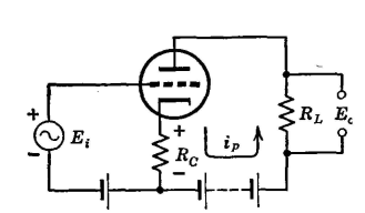
Current Feedback.24 The circuit of Fig. 32 produces negative current feedback. The positive half cycles of applied grid signal voltage cause the current from plate to cathode (inside the tube) to increase causing a voltage drop across Rc as indicated. The negative half cycles cause the current to decrease, producing a voltage drop across Rc opposite to that of Fig. 32. This alternating voltage drop across Rc is in opposition to the grid signal voltage and negative feedback results. The feedback factor is
|
|||
| Home Electronic Applications in Communication Feedback |
|
||

Last Update: 2011-05-30