| Electrical Communication is a free textbook on the basics of communication technology. See the editorial for more information.... |
|
Home  Electronic Applications in Communication Wideband Amplifiers Electronic Applications in Communication Wideband Amplifiers |
|||||


|
  |
||||
Wideband AmplifiersFor applications such as television, amplifiers that will pass very wide frequency bands; such as from 30 to 4,500,000 cycles, are required. If a pentode resistance-coupled amplifier is constructed with low plate load resistances, the high-frequency response is extended. Low-frequency compensation is achieved by a parallel R-C combination in series with the load resistor. High-frequency compensation is achieved by a small coil in series with the load resistor. These are called compensated amplifiers. Other types of wideband amplifiers are possible.25,26,27
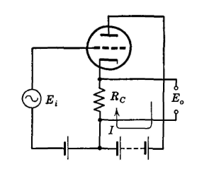
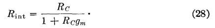
The input capacitance of the following tube plus the wiring capacitance are important factors limiting the high-frequency response (page 289). For this reason, a circuit called the cathode follower28 is often used between two wideband amplifying stages. The circuit arrangement is shown in Fig. 33. The cathode follower has a grid-input capacitance that is much less than the actual capacitance between grid and cathode. The grid-input impedance is correspondingly high. The internal impedance as measured at the output terminals is a low resistance
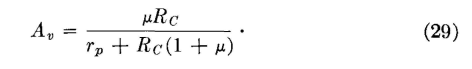
The cathode follower acts like a step-down transformer and can be used for impedance matching. The output voltage and the input voltage are in phase. The "voltage gain" is less than unity and is
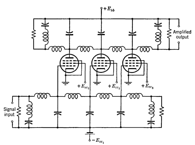
A new approach to the design of wideband amplifiers is the so-called distributed amplifier.29 In this amplifier two identical artificial transmission lines, composed of sections of inductance and capacitance
(which may include the interelectrode capacitances), are used. The grids of several tubes are connected in "parallel" across successive sections along one line, and the plates are connected in "parallel" across corresponding sections of the other line, the arrangement being shown in Fig. 34. The lines are, of course, low-pass filters (page 168). They are terminated with m-derived sections. The cutoff frequency is made considerably higher than the maximum frequency to be amplified, and the input impedance is essentially pure resistance, equaling the iterative impedance of the artificial line. If an input signal voltage is impressed, the first tube amplifies this signal and impresses an output signal on the upper line. This signal divides equally, part passing to the left, where it is lost, and part going toward the right. The input signal travels toward the right on the grid line, where the amplifying action is repeated, and the output signal impressed on the plate line again divides, part going to the left, where it is lost, and part going toward the right, where it is joined by the signal traveling to the right from the first tube. In this way, the signals from the successive tubes build up, giving an amplified output. An amplifier, constructed as shown in Fig. 35, was found to have a voltage gain of about 9 decibels from zero cycles to 40,000,000 cycles, and the band width can be made wider if desired.
|
|||||
| Home Electronic Applications in Communication Wideband Amplifiers |
|
||||
Last Update: 2011-05-30