| Electrical Communication is a free textbook on the basics of communication technology. See the editorial for more information.... |

|
Home  Telephone Exchange Service and Systems Operation of the Common- Battery, Multiple Switchboard Telephone Exchange Service and Systems Operation of the Common- Battery, Multiple Switchboard |
|||||


|
  |
||||
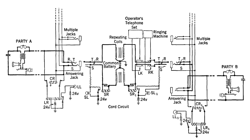
Operation of the Common-Battery, Multiple SwitchboardIn Fig. 16 is shown a simplified circuit of a typical common-battery multiple switchboard. The operation of this board when a call Is completed from a party in one central office to a party in the same central-office district will now be considered.
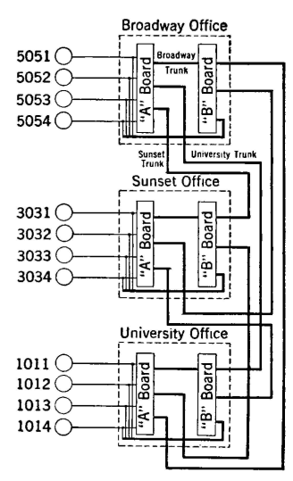
To call the operator the customer at A removes the receiver from the hook, thus allowing the switch to close and permitting current to flow from the battery up through the line relay LR, through the line wires, and through the transmitter of set A. This energizes the line relay, pulling up the armature and lighting the line lamp LL in the face of the switchboard near the line answering jack. Upon observing the lighted lamp, the operator inserts the plug of an answering cord into the answering jack indicated by the lighted line lamp. When this plug is inserted, the "tip," "ring," and "sleeve" (indicated by T, R, and S) connections are made. The cutoff relay CR is then energized over the circuit completed by the sleeve connection from the battery below the supervisory lamp SL, and the armature is pulled up, opening the line-lamp circuit. At the same time direct current flows from the central-office battery through the supervisory relay, SR, pulling up the armature of this relay, which shunts the lamp SL and prevents it from lighting. This direct current provides the transmitter talking current. The operator's set is connected by throwing the listening key LK, and the desired number is taken by the operator. The talking currents are shunted through the non-inductive windings shown above the supervisory relays SR and thus do not have to pass through the inductive windings. After ascertaining the desired number, the operator tests the called line by tapping the sleeve of the multiple jack of that line with the tip of the plug of the calling cord associated with the answering cord previously used. A click notifies the operator that the line is busy. If the line is not busy, the operator inserts the plug in the jack. When this is done, the tip, ring, and sleeve connections are completed, but, owing to the fact that the receiver is on the hook, no transmitter current flows to the called telephone, and thus the supervisory relay SR1 does not operate. Current therefore flows through the supervisory lamp SL1, through the sleeve connection and the windings of the cutoff relay CR1, and thus the lamp SL1 burns brightly. Also, the relay CR1 pulls up the armatures opening the contacts in series with the line relay LR1. When the ringing key is operated, the calling party is disconnected from the line, and the bell of the called party is rung. When the called party removes the receiver from the hook, the transmitter current flows through the relay SR1, pulling up the contact and extinguishing the lamp SL1 by shunting it. The talking circuit has now been established, and conversation takes place. Each station receives direct current for the transmitter from the central-office battery through the repeating coil windings. Transfer of energy of the talking currents from one part of the circuit to the other is made possible by the repeating coils. When either or both parties replace the receivers on the hook, the direct-current path is broken, and the two supervisory relays release, removing the shunts from the supervisory lamps, thus permitting them to light and to signal the operator to remove the connection. Telephone Service in Multioffice Exchanges. In a large exchange consisting of many central offices a small percentage of the incoming calls from the lines connected to an office is completed within that office. Many of the incoming calls are for telephones connected to other offices and must be transferred for completion over trunks connecting the two offices. As the number of trunk jacks is increased (Fig. 15), there is less room for the calling multiple jacks; also, this multiple is used less, and the trunk jacks more. Furthermore, in each central office additional separate multiples must be provided for completing calls trunked to that office from other offices. A point is therefore reached at which it is best to trunk all calls before completion even though some of the calls may be for lines connected to the office originating the call. In the offices of multioffice exchanges it is common to have the functions of answering and completing the calls performed by two operators working at separate boards. These are known as "A" and "B" operators, and the switchboards at which they work as "A" and "B" boards. The "A" operator takes the incoming calls, and the "B" operator completes the calls. The overall working of a typical system is illustrated schematically in Fig. 17.
In considering this system, assume that the party using line 5051 connected to the Broadway office wishes to talk to Broadway 5054. The "A" operator will place a cord-circuit plug in the jack of the calling line and will take the call as explained in the preceding section. Instead of completing the connection, the "A" operator will pass the call to a "B" operator for completion. In one system that has been used, the "A" operator calls the Broadway "B" operator over a call circuit, and states "Broadway 5054." The "B" operator assigns a vacant Broadway trunk to the "A" operator, who then inserts the other end of the cord which is being used in the 5051 answering line jack into this vacant trunk jack. The "B" operator then completes the call by placing the plug of the trunk assigned to the "A" operator in the calling multiple of the desired line. The called party is then rung, usually automatically. If the party using the line 5051 of the Broadway office desires to talk to University 1014, the procedure is similar. When the line lamp lights, indicating that a call is to be placed, the operator answers by plugging an answering cord into the calling line jack. The operator, informed that University 1014 is desired, passes the call to a "B" operator in the University office much as explained in the preceding paragraph. The call-circuit method of passing calls was considered in the preceding discussion. Often the straightforward method is used. With this plan of operation, the number that is desired is passed by an "A" operator to a "B" operator over the circuit that is used for completing the call.ref.15 The magnitude of the task of switching telephone calls is indicated by Fig. 18.
|
|||||
| Home Telephone Exchange Service and Systems Operation of the Common- Battery, Multiple Switchboard |
|
||||
Last Update: 2011-05-30