| Electrical Communication is a free textbook on the basics of communication technology. See the editorial for more information.... |

|
Home  Telephone Exchange Service and Systems Operation of the Crossbar System Telephone Exchange Service and Systems Operation of the Crossbar System |
|||||


|
  |
||||
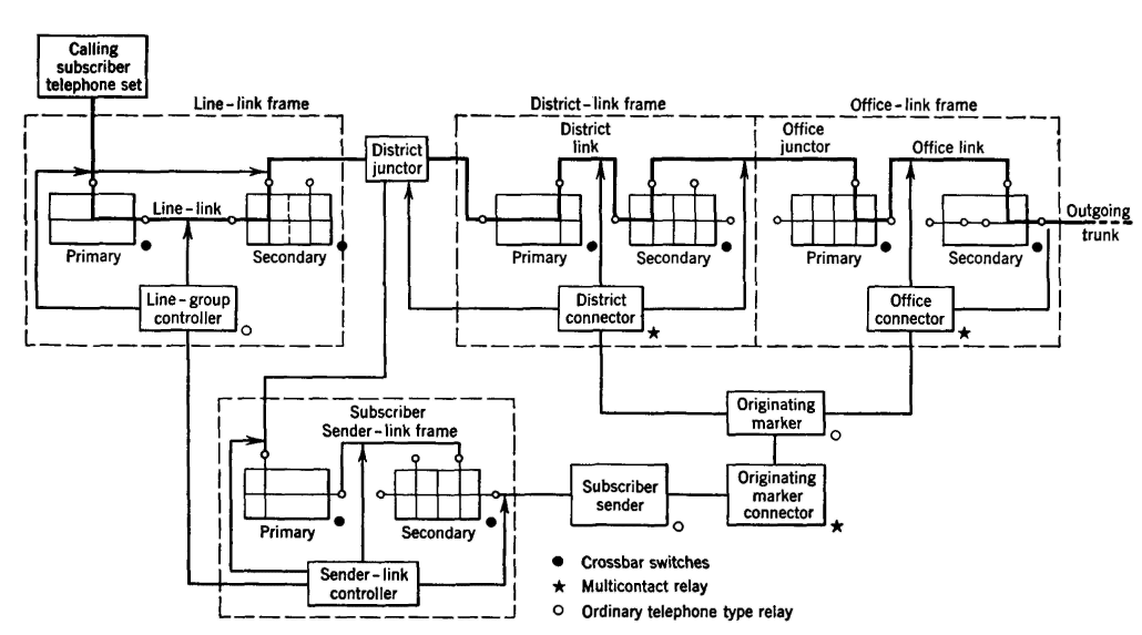
Operation of the Crossbar SystemIn the crossbar system the selection of the talking path is under the control of three common-controller circuits. The switching frames are as follows: line-link frame, district-link frame, office-link frame, and incoming-link frame. The district, office, and incoming frames of the crossbar office are used for the same switching functions as the district, office, and incoming selector frames of the panel office, but the line-link frame may be considered as two frames since it does the work of two frames. On outgoing calls it acts like a line finder connecting the calling line to the district-link frame; on incoming calls it connects the trunks from the incoming frames to the called line. Each crossbar frame consists of primary and secondary switches. The connections between these two sets of switches in the same frame are called "links," and the connections between frames are called "junctors". The progress of a call through a crossbar system can be divided into the four following stages. First Stage. When the calling party lifts the handset or the receiver, the line relay operates and seizes a line-group controller circuit that is common to the line-link frame associated with the calling line (Fig. 33). This control circuit finds the calling line and simultaneously selects a path to an idle district junctor. Before an idle line link to the district junctor is chosen, the control circuit determines which of the district junctors are available to the line links and also determines which of these has access to an idle sender. The primary selection is then made, connecting the line link through to the district junctor. This junctor is connected to a particular sender-link frame, and the associated sender-link control circuit then selects an idle subscriber. After this connection is completed between the calling line and the originating or subscriber sender, the two control circuits are released and made available for other calls. The originating subscriber sender furnishes dial tone to the calling party, indicating that dialing may be started.
Second Stage. The originating, or subscriber, sender connects to the originating marker through its connector circuit, and, as the number is dialed, the sender transfers the called-office code and the district-link frame identification to the marker circuit. Through the identification of the district junctor that has been chosen, the marker knows the incoming end-point for this stage of the connection. Also, by selecting an idle trunk leading to the called office, the marker can establish the outgoing end-point for this stage of the connection. Now the marker selects an idle path between these two points to complete this stage of the connection. This path will consist of three sections: the district link, office junctor, and office link. Some of these possible paths may already be in use on calls of other combinations; therefore the marker tests each link of a path before choosing the route. When the marker has completed the connection between the district junctor and the outgoing trunk, it checks the connection to ensure that it has been properly made and then releases itself from the connection. The connection is then held under the control of the district junctor. The marker completes its functions in approximately 0.5 second and then is released for use on other calls. When the district junctor has been connected to the outgoing trunk, the originating sender closes a bridge across the trunk conductors, thus operating the line relay of the incoming trunk circuit in the terminating office. Third Stage. The sender-link control circuit (Fig. 34) associated with the sender-link frame on which the incoming trunk appears establishes a connection between the incoming trunk and the terminating sender. This sender-link control circuit is then released for other calls. At this time the calling subscriber is still connected to the originating sender, and the dialing may not yet be completed. When the dialing is completed the originating sender transfers the dialed number to the terminating sender and then releases itself from the connection. The calling line is now connected through the district junctor to the incoming trunk.
Fourth Stage. The terminating sender now has the dialed number, connects to the terminating marker through the terminating-marker control-circuit, and transfers the called line number and the incoming-link identification to the marker. The marker then sets up a preliminary connection to the called line through the associated "number-group connector" and a frame on which the called line appears in numerical sequence. The marker tests for a busy condition. If the called line is idle, the terminating marker will connect through the line-choice connector to the line-group control circuit. The marker must then select an idle path through the incoming-link frame and the line-link frame in a manner similar to that used in the district-link and office-link frames. This path will consist of three parts: an incoming link, line junctor, and line link. After the connection is made to the called line, the marker causes the incoming trunk circuit to start the ringing of the called line and return ring-back tone to the calling line. The terminating marker, sender, and sender-link frame are then released, and the transmission circuit between the calling and called line will be completed when the called party answers. When the terminating marker finds the called line busy, it will cause the incoming trunk circuit to return busy tone to the calling line.
|
|||||
| Home Telephone Exchange Service and Systems Operation of the Crossbar System |
|
||||

Last Update: 2011-05-28