| Electrical Communication is a free textbook on the basics of communication technology. See the editorial for more information.... |

|
Home  Telephone Exchange Service and Systems The Crossbar Switch Telephone Exchange Service and Systems The Crossbar Switch |
|||||


|
  |
||||
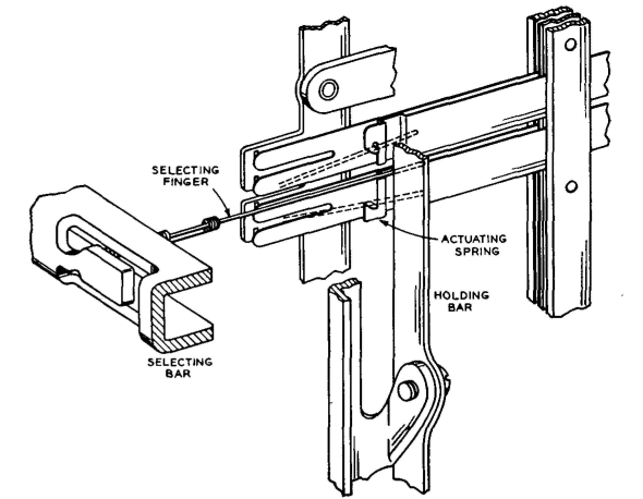
The Crossbar SwitchThe crossbar switchref.29 is the basic unit. This switch consists of three major parts: first, 20 separate vertical-circuit paths; second, 10 separate horizontal-circuit paths; and third, a mechanical means of connecting any one of the 10 horizontal-circuit paths to any one of the 20 vertical-circuit paths by the operation of electromagnets. The 20 vertical units consist of a multiple relay-like structure having 10 sets of contacts in each vertical row and a holding electromagnet. There are five horizontal bars, each provided with 20 selecting fingers (Fig. 31) made of wire. There are two electromagnets associated with each horizontal bar so that it can be operated in either of two directions. The selecting fingers are mounted at right angles to the bar, with one finger at each vertical row of contacts. When the selecting bar is rotated through a small arc by one of its electromagnets, the selecting fingers move up or down into a position such that, if one of the holding bars (Fig. 31) is operated by its electromagnet, the selecting finger at the crosspoint of the two bars will operate the set of contacts at that point. The selecting bar can then be released, and the selecting fingers not being used will return to normal, but the one finger used to operate the contacts will remain latched under control of the holding bar.
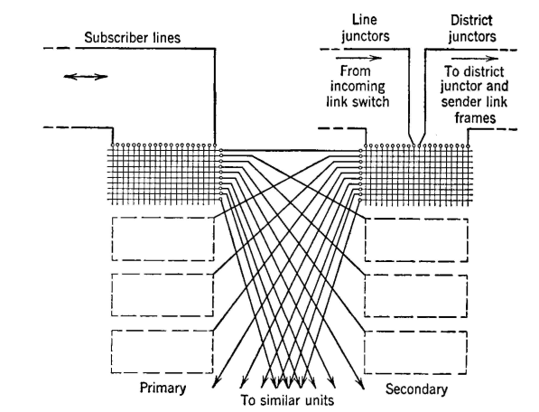
A single crossbar switch (Fig. 32) having 200 points with 20 vertical units, each connected to a subscriber line, and 10 trunks wired to the horizontal units, provides an arrangement for any one of the 20 lines to be connected to any of the 10 trunks. The addition of other switches, which have their vertical units wired to other groups of 20 lines and connect the horizontal units in multiple (parallel) to the horizontal units of the first switch, will provide additional lines having access to the same 10 trunks. Still greater trunking access may be obtained by using two groups of switches, referred to as "primary" and "secondary" in a link frame. A link frame (Fig. 32) is made up of 20 crossbar switches arranged in two vertical files of 10 primary and 10 secondary switches. Each primary switch has 20 lines connected to the vertical units, and 20 trunks are connected to the vertical units of each secondary switch.
The horizontal multiple of each primary switch is connected (Fig. 32) to the horizontal multiple of the secondary switches so that each primary switch has one horizontal path connected to each of the 10 secondary switches. This gives any of the 200 lines access to any of the 200 trunks on the secondary switches.
|
|||||
| Home Telephone Exchange Service and Systems The Crossbar Switch |
|
||||
Last Update: 2011-05-30