| Electrical Communication is a free textbook on the basics of communication technology. See the editorial for more information.... |

|
Home  Telephone Toll Service and Systems The V1 Repeater Telephone Toll Service and Systems The V1 Repeater |
|||


|
  |
||
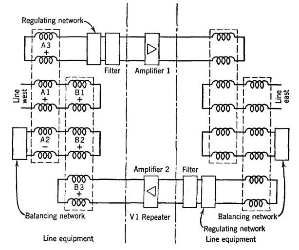
The V1 RepeaterThe basic 22-type repeater and the modifications 22A1 and 22A2 were standard from about 1915 to 1940. In these, hybrid coils, balancing networks, filters, etc., which in a sense are as much line equipment as repeater equipment, were associated with the amplifying elements. About 1940 the V1 repeater17 was perfected. This is a voice-frequency repeater in which the line equipment is physically separated from the amplifying units, giving increased flexibility, reduction in space requirements and cost, and other advantages. A simplified diagram of the V1-repeater arrangement is shown in Fig. 10. The center portion, consisting of the amplifiers, is mounted, together with amplifiers of other similar repeaters, in one location. The two end portions, consisting of line equipment, are at another location. Of importance is the fact that two transformers, or repeating coils, instead of a hybrid coil, are used to connect to the incoming circuits. The operation is summarized17 as follows: The + and - signs adjacent to the windings of the repeating coils indicate the relative "poling" of the windings; that is, they indicate the relative directions of the induced voltages. A speech signal coming from line west passes through coils A1 and B1 and produces equal magnetic fluxes in the cores of each transformer. The flux in the core of transformer A induces voltages in windings A2 and A3, and the flux in the core of transformer B induces voltages in windings B2 and B3. The voltages induced in A2 and B2 are opposite in sign, and the design is such that there is complete cancellation and no current flow in the balancing network if the impedances connected to A3 and B3 are equal.
The energy coming in over line west divides equally between the input to the upper branch, where it is amplified and passed to the line east at the right, and the output to the lower branch where it is dissipated. An amplified speech signal, such as that coming from the lower amplifier passes through winding B3 and produces a magnetic field in the core of transformer B. This magnetic field induces voltages in the B1 and B2 windings, and these voltages cause current to flow to line west and to the associated balancing network. If the line impedance and the network impedance are equal, these currents produce no magnetic flux in the core of transformer A, because windings A1 and A2 are opposite in their magnetic action. Thus, no current flows through the A3 winding and into the input of the upper amplifier, preventing singing. The signal energy from the lower amplifier divides equally between line west and the associated balancing network, and none goes to the upper amplifier. Later developments in repeaters have retained the basic V1-repeater principles.
It appears possible (1949) that repeaters of the future may be affected by the development of the transistor.
|
|||
| Home Telephone Toll Service and Systems The V1 Repeater |
|
||
Last Update: 2011-05-30