| Electrical Communication is a free textbook on the basics of communication technology. See the editorial for more information.... |

|
Home  Telephone Toll Service and Systems Repeater Applications Telephone Toll Service and Systems Repeater Applications |
|||||||||


|
  |
||||||||
Repeater ApplicationsThe function of a telephone repeater is to amplify the weakened currents at various points along the line or cable. The manner in which this was accomplished for an early transcontinental open-wire connection is illustrated by Fig, 11. It may appear that all the amplification could be supplied at the sending end instead of at various points along the line. That this is impracticable is shown by the following statement:18
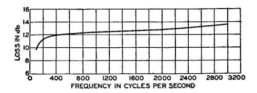
Let us suppose, however, that a 50,000-kilowatt generator delivered its entire output to the circuit at San Francisco, and overlook, for the moment, what would happen to the line if any such amount of energy were applied. The power received at New York would be of the order of one five-hundredth of a microwatt, which would have to flow for about 25,000 years in order to equal the energy required to light a 25-watt lamp for one minute.(1) It may seem possible to do all the amplifying at the receiving end. This cannot be done because the ratio of the useful speech currents to the undesired noise current level must always be kept high. If at any time the level of the speech currents fall below the noise currents, then at the receiver the noise will be greater than the speech. Repeaters must be installed at regular intervals along a line. In Fig. 12 is shown the loss at various frequencies over a 30-mile loaded cable section. This loss, it is seen, varies with frequency. Not only does the repeater amplify the speech current and overcome the loss, but it also corrects the frequency distortion.15
On long aerial toll cables special provisions must be made to compensate for changes in attenuation caused by temperature variations affecting the resistance and to some extent the capacitance of the circuits.19 This is sometimes accomplished by a Wheatstone-bridge arrangement. Two vacant wires in the cable are connected to form one side of a bridge. The change in resistance of these wares operates the bridge mechanism, which in turn changes the repeater amplification to compensate for the greater or less line attenuation. Repeaters are applied to voice-frequency circuits in several forms. First, they are installed at various points along an open-wire line or cable circuit, in which event they are called1 intermediate repeaters, or sometimes through-line repeaters. Second, they are installed at the ends of transmission circuits and are hence called1 terminal repeaters. Third, repeaters may be installed in the cord circuit of a toll switchboard and are hence called cord-circuit repeaters. The toll operator uses this particular cord circuit for interconnecting toll lines having high loss. Formerly this practice was widely used, but in modern systems most toll circuits are provided with repeaters (if necessary) and are so designed that for all possible connections the loss is not excessive.3
|
|||||||||
| Home Telephone Toll Service and Systems Repeater Applications |
|
||||||||

Last Update: 2011-05-30