| Electrical Communication is a free textbook on the basics of communication technology. See the editorial for more information.... |

|
Home  Telephone Toll Service and Systems Type J Carrier Telephone System Telephone Toll Service and Systems Type J Carrier Telephone System |
|||||


|
  |
||||
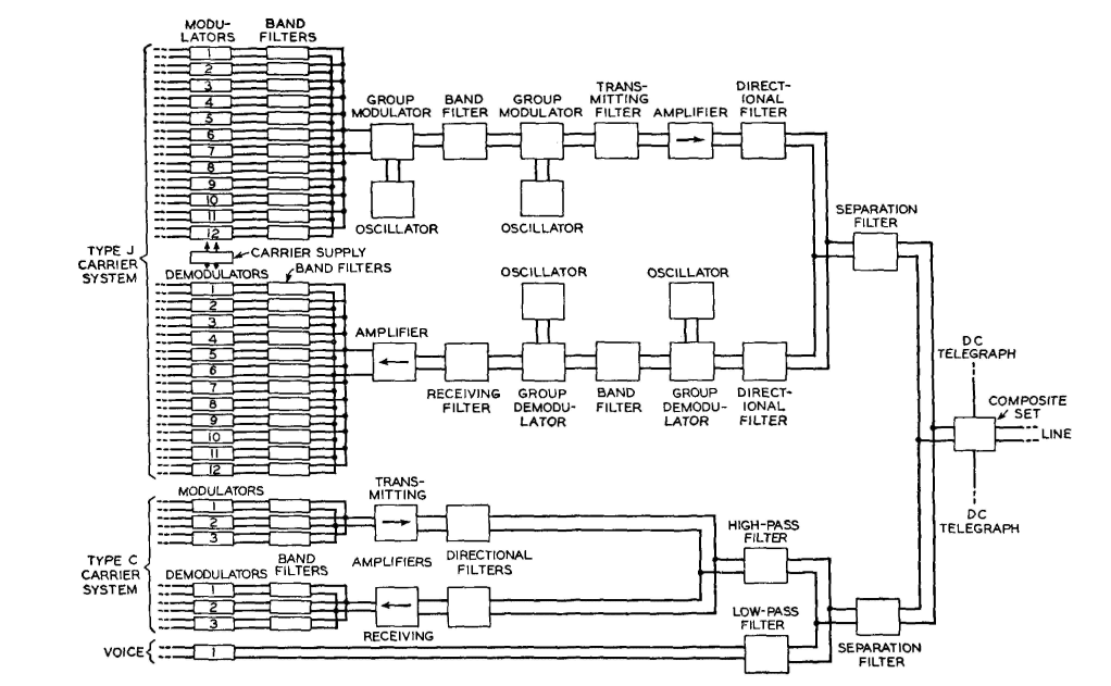
Type J Carrier Telephone SystemThe type J carrier43,44,45 is designed for open-wire lines and operates in the region from about 36,000 to 140,000 cycles. Twelve talking channels are provided. A voice-frequency circuit and a type C carrier can operate simultaneously, giving a total of 16 channels over one pair of wires, as shown by Fig. 27. As Fig. 18 indicates, the band from 36,000 to 84,000 cycles is used for talking in one direction, and the band from 92,000 to 140,000 cycles is used for talking in the other direction. The incoming voice-frequency signals pass through hybrid coils (not shown in Fig. 27) and are there changed from two-wire to four-wire circuits as in any repeater or carrier circuit. Each of these voice-frequency signals is then impressed on one of the modulators at the top of Fig. 27. The carrier frequencies used with these modulators cover the band from 64 to 108 kilocycles. The lower sidebands of the outputs of these modulators are selected by the band filters and combined into a group. This group of from 60 to 108 kilocycles passes into the group modulator, which is supplied with a 340-kilocycle carrier frequency from an oscillator. Here modulation of the group occurs, and the band filter selects the group upper sideband that extends from 400 to 448 kilocycles. This group of frequencies is then impressed on a second group modulator together with a frequency of 484 kilocycles, if the system is for transmitting from west to east. The group lower sideband will be a group of frequencies extending from 36 to 84 kilocycles which is selected for transmission. This group contains the information of the twelve incoming voice-frequency channels. For east to west transmission, the last modulator uses a carrier frequency of 308 kilocycles, and the group of frequencies will be at 92 to 140 kilocycles for talking in the east-west direction. For receiving, the opposite sequence of translation is used. Repeaters in Type J Carrier Systems.43 Repeaters are required at 75- to 100-mile intervals, depending on wire sizes, etc. Even a very thin coating of ice on the line wires causes a great increase in the line attenuation, and, in areas where ice often forms, repeaters may be spaced about 50 miles apart. Pentode vacuum tubes are used in the amplifiers, which are of the negative-feedback type (page 300). Regulating amplifiers with pilot control are provided at intervals.
In the center is shown a later construction (about 1925) with 8-inch spacing, except for pole pairs, and with 24-inch spacing between crossarms. One type C carrier system (3 channels) and one voice-frequency circuit operate on each of the 8-inch spaced pairs. Voice-frequency circuits operate on the pole pairs which are phantomed. With this arrangement 22 voice-frequency circuits and 48 carrier circuits are provided, giving a total of 70 two-way telephone channels. At the right is shown a more recent construction (about 1940). The spacing of wires of a pair is 8 inches, the pole pairs are omitted, and the crossarms are spaced 36 inches apart. One voice-frequency circuit, one type C carrier (3 channels), and one type J carrier (12 channels) operate on each pair, giving 16 voice-frequency circuits, 240 carrier circuits, and a total of 256 two-way telephone channels. (Reference 43.) Crosstalk in Type J Carrier Systems.43,44 Because of the serious crosstalk problem existing at the high frequencies used in this carrier system, a special transposition system (Chapter 14) was designed. Also, a new wire spacing of 8 inches between wires of a pair and 8 wires per crossarm was adopted (Fig. 28). Furthermore, transposition poles were more accurately located, and wire sags were reduced and equalized.
|
|||||
| Home Telephone Toll Service and Systems Type J Carrier Telephone System |
|
||||

Last Update: 2011-05-30