| Electrical Communication is a free textbook on the basics of communication technology. See the editorial for more information.... |

|
Home  Telephone Toll Service and Systems Type K Carrier Telephone System Telephone Toll Service and Systems Type K Carrier Telephone System |
|||||||


|
  |
||||||
Type K Carrier Telephone SystemThe original type K1 multichannel carrier telephone system was designed for non-loaded cables and was placed in service about 1938. This provided 12 talking channels, and approximately 2,500,000 miles of two-way telephone message circuits were installed.46 About 1944 an improved system, the type K2, was developed, and by 1947 an additional 2,500,000 circuit miles had been placed in service.46 Because the wires of a cable are so close together, there is a very great tendency for an exchange of energy to occur between circuits, resulting in serious crosstalk (page 565). This is true particularly at high frequencies, and in general the use of carrier in cables had been avoided prior to the development of the type K system. One factor that has made these systems possible is the use of separate cables for talking in the two directions. Or the same cable structure may be used, but the inner conductors are used for transmission in one direction, and the outer conductors used for transmission in the other direction, and a suitable shield is placed (during manufacture) between the two groups. In this way coupling between high-energy circuits, emerging from a repeater and low-energy circuits, just entering a repeater, is avoided.
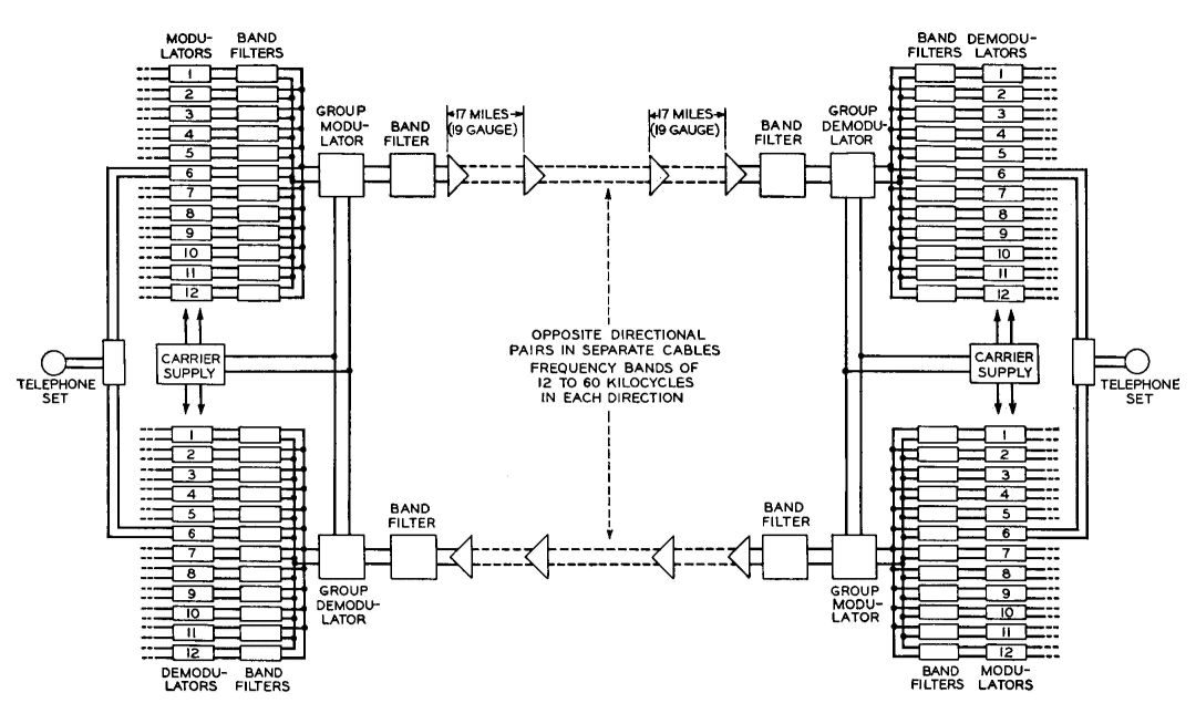
Type K1 Carrier System. A block diagram of a type K1 system41,47 is shown in Fig. 29. Because separate cables are used for transmitting and receiving, the same numerical group of frequencies may be used for each direction, and hence the system is simplified as compared with the type J carrier. Briefly, the operation of the type K1 system is as follows: As indicated in Fig. 29, each of the 12 connected telephone sets feeds in through a hybrid coil (shown as a block) that separates the transmitting and receiving functions. The signal to be transmitted is impressed on a copper oxide modulator. The various carrier frequencies (obtained as explained for the type J system) are shown by arrows in Fig. 30. They are made high so that crystal filters can be used, and for other reasons.
After modulation, the lower sidebands are combined and fed in common to a group modulator together with a carrier frequency of 120 kilocycles. The lower sideband of this group is selected for transmission. Thus, the various telephone conversations are transmitted over the cable within the band 12,000 to 60,000 cycles. At the receiving end they are restored to their original audible frequencies by a similar double-demodulating process. Repeaters in Type K1 Carrier Systems47 As indicated in Fig. 29, repeaters are placed in the cable circuits at about 17-mile intervals. Because separate cable pairs are used for transmitting in the two directions, at a repeater point two one-way vacuum-tube amplifiers are installed. As previously stated, the cable pairs used for type K systems are non-loaded, the reason being evident in Fig. 31. The wave velocity is about 100,000 miles per second which minimizes echo effects and reduces difficulties in conversation.47, 48 As Fig. 31 indicates, temperature changes cause decided variations in cable attenuation. Temperature variations of underground cable occur slowly and ordinarily are not extreme, but for aerial cables the opposite is true. When the sun is shining directly on a lead-covered aerial cable the cable temperature may rise from 15° to 25° F. above that of the surrounding air; then, within a few minutes, the cable may be subjected to cold rain, following a thunder storm. The attenuation change with temperature variations for a cable is composed of two parts: first, a component that is independent of frequency, and second, a component that varies with frequency and is called47 twist. The pilot-wire method (page 408) and automatic repeater gain adjustments are used to maintain the transmission at the correct level.
Crosstalk and Noise in Type K1 Carrier Systems.47,49 As has been explained, to reduce crosstalk, circuits in different cables and shielded circuits have been used for transmitting and receiving. This minimizes what is called near-end crosstalk1 (page 565) in the cables, and special precautions are taken to minimize crosstalk in office wiring. Far-end crosstalk1 (page 566) between adjacent pairs transmitting in the same direction is reduced by connecting small adjustable mutual inductance balancing coils between the circuits and by other means. Noise originating in repeater stations is reduced by filters. Improved Type K2 Carrier System.46 The basic circuit arrangement is the same as described for the type K1 carrier. The K2 carrier is particularly suited for transcontinental cable operation, gives improved performance, and is more economical than the older type. The most important changes are in the repeaters. Three types of amplifiers are used: transmitting amplifiers that are inserted only at the transmitting end; twist amplifiers that are placed about 100 miles apart on aerial cables, about 250 miles apart on underground cables, and compensate for the twist previously discussed; and line amplifiers that are placed approximately 17 miles apart. Line amplifiers do three things:46 first, they compensate for the loss in the preceding cable section; second, they equalize for variations in loss at the different frequencies; and third, they regulate the gain automatically. Feedback amplifiers with thermistor (page 310) control to adjust the gain are employed.44
|
|||||||
| Home Telephone Toll Service and Systems Type K Carrier Telephone System |
|
||||||


Last Update: 2011-05-30