| Electrical Communication is a free textbook on the basics of communication technology. See the editorial for more information.... |
|
Home  Radio Systems The Superheterodyne Radio Receiver Radio Systems The Superheterodyne Radio Receiver |
|||||


|
  |
||||
The Superheterodyne Radio ReceiverAs previously mentioned, the superheterodyne is almost universally used. The name means little from the standpoint of the electrical principle of operation. It has been called a double-detection receiver.
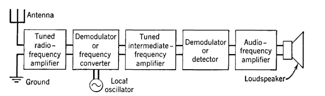
A block diagram of the superheterodyne radio receiver is shown in Fig. 13. The functioning of a tuned-radio-frequency amplifier has been explained. The demodulator (also called first detector, converter, or mixer) operates as follows: Suppose that the amplitude-modulated signal of page 489, composed of a one-megacycle carrier and two sidebands, has been received and is impressed between grid and cathode of the frequency converter. Also, at this same time assume that a single frequency of 1,455,000 cycles is impressed between grid and cathode of the converter, which is a vacuum tube operated so that non-linear distortion occurs. Sum and difference frequencies will be produced by this tube, and among the several new frequencies there will exist the components of 455,000 cycles, 455,100 to 460,000 cycles, and 454,900 to 450,000 cycles. These are the carrier and the two sidebands translated, or moved down, to a new location in the radio spectrum. All the information of the original modulating signal now exists at these new frequencies; hence the term frequency converter. It should be remembered, however, that the basic principle involved is the same as that of the usual modulating circuit; that is, one of non-linear distortion and the creation of sum and difference frequencies. The high selectivity of the superheterodyne is achieved through the selective action of the intermediate-frequency amplifier. This is a carefully tuned radio-frequency amplifier (page 290) of high voltage gain, that is adjusted to amplify and pass a band of about 450,000 to 460,000 cycles only, and to offer much attenuation to other frequencies. This amplifier will amplify the carrier and sidebands at the "intermediate frequencies" of the preceding paragraph. If an unwanted station exists at a carrier frequency of 1,020,000 cycles and if some of this signal is passed by the tuned-radio-frequency amplifier, this also will react with the 1,455,000-cycle signal from the local oscillator and produce a difference-frequency band centered at 475,000 cycles. This would be too high to pass through the intermediate-frequency amplifier, If it is desired to receive the 1,020,000-cycle station and reject the 1,000,000-cycle station, this can be accomplished merely by adjusting the local oscillator to 1,475,000 cycles. The selected and amplified signal passing through the intermediate-frequency amplifier (usually called an I-F amplifier) is impressed on another demodulator, or second detector, as it is usually called. In this, sum and difference frequencies are produced from the so-called intermediate frequencies. That is, sum frequencies of about 1,000,000 cycles will be produced, and difference frequencies of from 100 to 5000 cycles will be produced. The difference frequencies are the desired audio-frequency band containing the information or program transmitted from the distant station. The diode detector shown in Fig. 14 (a) is the demodulator or second detector in the superheterodyne radio receiver. The tube shown is a combination diode and triode. The diode portion is used for demodulation, and the triode portion for amplification. These two functions are shown separately in (b) and (c). The carrier and two sidebands, existing at the intermediate frequencies, arc simultaneously distorted in the diode rectifying portion (b), and the desired audio-frequency component, containing the transmitted message or program, is created. This will flow through the circuit composed of the 150-micromicrofarad capacitor and 1.0-megohm resistor in parallel. The impedance of this combination is such that the audio-frequency components will cause considerable voltage drop, but the radio-frequency components will cause negligible voltage drop. A part of the audio-voltage drop across the 1.0-megohm resistor is selected by the manual volume control, indicated by the arrow head on this resistor, and this voltage is impressed between the grid and cathode of the triode portion of the tube. The tubes often used have amplification factors of 100 for the triode portion, and considerable audio-frequency voltage amplification is produced in this stage.
An automatic-volume-control voltage is obtained between point X and ground in Fig. 14(a). Assume that the radio set is tuned to the carrier frequency of a station that is, for the moment, unmodulated. The carrier will be rectified in the diode part of the tube, a direct current will flow through the 1.0-megohm resistor, and a direct voltage will exist across it, with the X terminal negative. If the radio signal transmission path improves, because of ionospheric or other changes, a stronger signal will be received, the voltage drop will increase, and point X will be more negative. If the radio signal path becomes less efficient, point X becomes less negative. The automatic-volume-control voltage is obtained between point X and ground and is the voltage just discussed. This is impressed as a grid bias on a variable-mu or super-control tube. This is usually one of the pentode voltage-amplifying tubes used in the intermediate-frequency amplifier, and it is constructed so that the amplification factor varies widely with changes in the grid-bias voltage. Thus, when the received signal is strong, the automatic-volume-control voltage used as a bias is large and the tube is operated so that its amplification is low. When the received signal is weak, the bias is low and the amplification produced by the tube is high. The preceding discussion was for an unmodulated carrier signal only. When a modulated signal is received, an audio voltage also will exist between point X and ground. For this reason, the automatic-volume-control voltage is obtained from point X as follows: A resistor of about 2 megohms and a capacitor of about 0.05 microfarad are connected in series between point X of Fig. 14 and ground. The resistor, which is between point X and the capacitor, limits the capacitor charging and discharging current. Thus, the capacitor voltage does not vary at the audio rate, but only in accordance with the relatively slow changes caused by variations in the signal transmission path; this capacitor voltage is used as the automatic-volume-control voltage,
|
|||||
| Home Radio Systems The Superheterodyne Radio Receiver |
|
||||

Last Update: 2011-05-30