| Electrical Communication is a free textbook on the basics of communication technology. See the editorial for more information.... |

|
Home  Radio Systems Antennas for Amplitude- Modulation Radio Receivers Radio Systems Antennas for Amplitude- Modulation Radio Receivers |
|||||


|
  |
||||
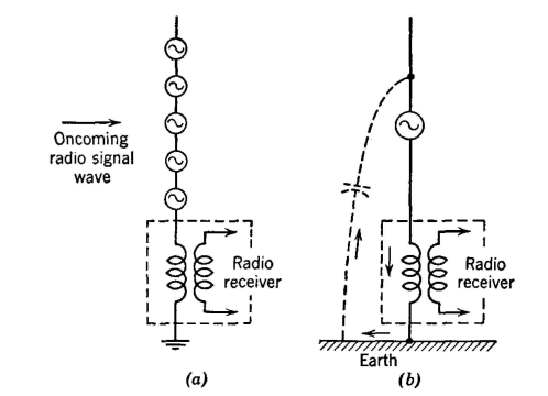
Antennas for Amplitude-Modulation Radio ReceiversFor point-to-point communication, the receiving antennas are engineered carefully (page 511). For standard amplitude-modulation broadcast reception (550 to 1600 kilocycles) the receiving antennas are usually of two types; first, "vertical straight-wire" types, and second, wire loops. The words were placed in quotation marks because an individual antenna may deviate far from this general classification. Vertical Straight-Wire Receiving Antennas. The oncoming radio signal wave, which is vertically polarized in amplitude-modulation broadcast reception, induces a signal voltage in each elemental length of the antenna as shown in Fig. 15(a). These voltages add vectori-ally18 and produce a current flow as indicated in (b). The current in the primary of the antenna coil induces a voltage in the secondary which is the voltage impressed on the tuned-radio-frequency amplifier circuit previously discussed. Loop Receiving Antennas. Many amplitude-modulation broadcast receivers utilize built-in loop antennas. There are many advantages to this, including the possibilities of noise reduction (Chapter 14).
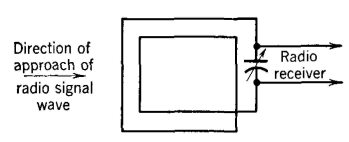
Whether the loop receives signal because the vertical wires (or parts thereof) are parallel to the arriving electric lines of force or because the plane of the loop is perpendicular to the arriving magnetic lines of force is a common question, and one which is discussed in reference 14 (see also page 576). The signal voltage induced in the wire loop causes a current to flow around the loop which is tuned to series resonance with the capacitor (Fig. 16). The voltage drop across the capacitor is the signal voltage to be amplified (page 499). On page 500 it was explained that a superheterodyne radio-receiving set contained a tuned-radio-frequency amplifier. In many superheterodynes this amplifier is omitted, and a tuned circuit or the tuned loop is used to give some initial selectivity. In very inexpensive (and often unsatisfactory) superheterodynes all tuning is omitted preceding the frequency converter. Such sets are bothered with the reception of image frequencies and with cross modulation. If the tuning ahead of the converter is omitted and if a 1,000,000-cycle station is being received, a station outside the broadcast band on an "image frequency" of 1,910,000 cycles will also be received. Cross modulation12 is a form of interference caused by the modulation of the desired carrier by an undesired signal.
|
|||||
| Home Radio Systems Antennas for Amplitude- Modulation Radio Receivers |
|
||||
Last Update: 2011-05-30