| Electrical Communication is a free textbook on the basics of communication technology. See the editorial for more information.... |

|
Home  Radio Systems Transoceanic High-Frequency Radio-Telephone Systems Radio Systems Transoceanic High-Frequency Radio-Telephone Systems |
|||||


|
  |
||||
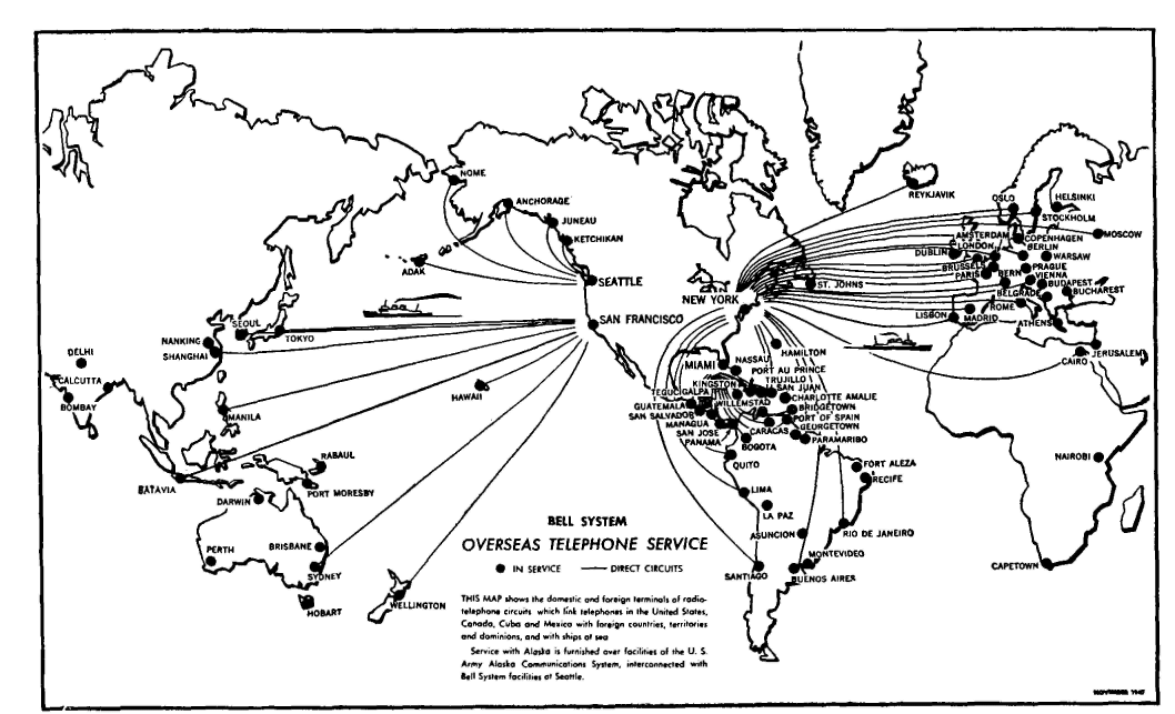
Transoceanic High-Frequency Radio-Telephone SystemsThe overseas radio-telephone connections of the Bell System are shown in Fig. 19. With the exception of the long-wave system just described, the facilities of Fig. 19 are provided over short-wave amplitude-modulation systems.21 Because of the large number of systems in use and because of changes made from time to time, it is not feasible to attempt to describe the systems in detail. Instead, an overall picture of short-wave radio-telephone facilities will be presented. The terminal arrangement of the equipment in a typical system is similar to that shown in Fig. 17. In the early systems Compandors were not used, noise reduction being achieved by voice control at the receiver.22 This is based on the principle that the presence of background noise reduces the sensitivity of the ear (page 41) and reduces the intelligibility of a signal. Loss is introduced into the circuit during the intervals of no speech. Then, when speech does occur, the ear will be more sensitive than if the noise had not been reduced, and the signal, even with the background of static, will be more intelligible. The original short-wave transoceanic radio-telephone systems transmitted the carrier and both sidebands; this is a wasteful process. For equal peak amplitudes in the transmitter, a system transmitting only one sideband gives a theoretical improvement of 9 db in received signal-to-noise ratio over a station transmitting the carrier and both sidebands.23 Notwithstanding the advantages of single-sideband transmission, it was not used in the early systems for reasons which will now be given. For single-sideband transmission, the carrier must be supplied for demodulation at the receiver by a local oscillator or by some other stable local source. For satisfactory speech demodulation, the local frequency must be within +/-20 cycles of the correct value.23 This offered no serious problem in the long-wave channel operating at 60,000 cycles, but such high stability was difficult to achieve in shortwave oscillators operating at several million cycles. To avoid this difficulty in the single-sideband short-wave systems installed in 1935 for transoceanic telephone purposes, a pilot frequency was transmitted over the system, in addition to the single sideband. For this purpose, some of the carrier (greatly reduced) of the transmitting set was transmitted along with one of the sidebands to the distant receiver, and thus the carrier itself acted as the pilot frequency. This weak received carrier signal may be used to synchronize automatically the locally generated carrier at the receiving station, or it may be amplified at the receiving station and then combined with the received sideband in the demodulator. Further details of the transmitters and receivers are given in references 24 and 25.
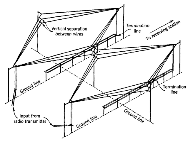
Transmitting Antennas for Radio-Telephone Systems. Originally, resonant broadside arrays were used in these systems.26,27 These were elaborate and costly and operated at one frequency only. Because each transoceanic telephone system is provided with several different frequencies for operation at different times (Fig. 18), it was necessary to have an antenna for each frequency. These resonant antenna arrays were soon replaced with non-resonant rhombics for both transmitting and receiving. For transmitting, a twin rhombic such as is shown in Fig. 20 is used. This gives characteristics better than a single large rhombic. On page 482, the rhombic antenna was shown terminated with a resistor to prevent wave reflection. The "termination line" of iron wire shown in Fig. 20 serves the same purpose and is used with large transmitting antennas.
Receiving Antennas for Radio-Telephone Systems. The rhombic antenna (page 482) is most receptive to a wave coming in at a small angle with the horizontal. This is important for at least two reasons: First, the antenna is less sensitive to sources of noise (such as automobile ignition systems) on the surface of the earth; second, by altering the antenna dimensions this angle of maximum sensitivity can be changed. For maximum reception, the angle at which the antenna is most sensitive should coincide with the angle at which most of the electromagnetic energy arrives at the receiving antenna location from the distant transmitting station. Thus by altering the dimensions the rhombic antenna may be steered28 to the most favorable direction. By this action, fading is reduced. Rhombic antennas, which remain mechanically fixed in a horizontal plane, may also be steered by electrical changes in the receiving circuit. Thus, as many as sixteen rhombic antennas are combined into an array called a Multiple Unit Steerable Antenna or MUSA, and such an array gives decided advantages in reception over a single rhombic antenna unit for the following reasons.21,29 Noise due to static and selective fading due to phase interference of signal components arriving over different paths are factors seriously affecting radio reception. The signal-to-noise ratio can be increased by using receiving antennas of sharper directional characteristics, but such antennas may be so highly directional as to "miss" the signal as it fluctuates, and they may thus have bad selective fading. Studies have shown that what is regarded as a received radio signal is in reality the combination of several signals arriving at the receiving antenna over various transmission paths. The ordinary directional receiving antenna is "blunt" enough to receive substantially all these components. Since they are of varying magnitudes and phases, however, their combined signal is not constant but fades, thereby causing variations and accompanying distortion in the receiver output. With the MUSA system, the individual signals picked up by a number of rhombic antennas are properly phased and then combined to give a large signal voltage. Strong incoming signals are separately "aimed at" by the individual MUSA units, and the received components are properly phased and then combined. Decided improvements, resulting in increased reliability of the short-wave systems, are obtained with MUSA arrays. It has been found that with high-frequency radio systems the received signal at a given frequency may momentarily grow weak at a certain location but may actually grow stronger at a point only a few hundred feet away. Also, at a given location the signal received on one frequency may momentarily grow weak, but the signal strength at the same location may become greater for a frequency a few hundred cycles different. Diversity receiving systems have been developed for both radio-telephone and radio-telegraph systems to take advantage of these facts.30,31 Systems are in use in which the signals from the same transmitting station, but received by two or more antennas spaced some distance apart, are properly combined to operate one receiving unit. These are termed space diversity receiving systems. Advantage is taken of the fact that transmission may be poor on one frequency but excellent on one a few hundred cycles different in the frequency diversity systems, in which the same receiving equipment is used but the signal is transmitted simultaneously at slightly different frequencies.
|
|||||
| Home Radio Systems Transoceanic High-Frequency Radio-Telephone Systems |
|
||||
Last Update: 2011-05-30