| Electrical Communication is a free textbook on the basics of communication technology. See the editorial for more information.... |

|
Home  Interference and Noise Telephone Transposition Schemes Interference and Noise Telephone Transposition Schemes |
|||||


|
  |
||||
Telephone Transposition SchemesA very elementary transposition scheme22,23,24 for crosstalk alone is shown in Fig. 11. A study of this diagram will indicate that, if the distance d is small, about one mile or less, each circuit will be inductively balanced with respect to each of the others, and thus excessive crosstalk will not occur.
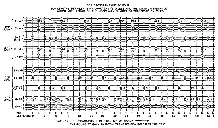
It is apparent that where many wires are involved, as in a four-arm line having 40 wires, transposition schemes become very complex. This is further complicated by the use of phantom circuits, for not only must crosstalk between side circuits be minimized but also crosstalk caused by phantoms must be reduced. From these discussions it should not be inferred that special transposition schemes are designed for each new line. In fact, quite the opposite is true; standard transposition systems23 are available and are used in new line construction. A standard scheme is shown in Fig. 12. Attention is called to the four different types of phantom transpositions indicated in the diagram. These, it will be observed, depend on the side-circuit transpositions at the phantom transposition points. When a new line is laid out, transposition schemes such as Fig. 12 are fitted in so that they best meet conditions, especially from the standpoint of coordination with existing or proposed power parallels. The complexity of phantom transpositions is evident from Fig. 12. In fact, the necessity for transpositions is one factor preventing the use of "phantoms on phantoms," often called "superphantoms" or "ghosts."
|
|||||
| Home Interference and Noise Telephone Transposition Schemes |
|
||||

Last Update: 2011-05-28