| Basic Radio is a free introductory textbook on electronics based on tubes. See the editorial for more information.... |

|

Home  Fundamentals Fundamentals  Alternating Currents Alternating Currents  A Simple A.C. Generator A Simple A.C. Generator |
||||||


|
||||||
|
A Simple A.C. GeneratorAuthor: J.B. Hoag When a conductor moves through a magnetic field, an e.m.f. is produced between its ends. This can drive a current through the wire, provided a complete circuit exists.
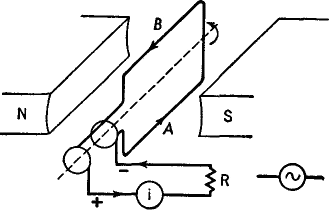
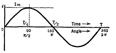
In Fig. 4 A, a loop of wire is rotated in a magnetic field. The ends of the loop are fastened to circular metal rings with brushes so that, as the coil rotates, the generated current can flow by way of the brushes to a load resistance R and a meter i. When the coil is in the vertical plane, its wires will be moving parallel to the magnetic lines of force and there will be zero e.m.f. and no current, as indicated at 0, Fig. 4B.
As the coil continues its rotation, B now moves up and to the right, while A goes down and to the left; A and B of Fig. 4 A are now interchanged; the e.m.f. and the current are reversed in direction. This is shown in Fig. 4 B, from T/2 to T. This is called the " negative half-cycle " of the current. Each time the coil rotates once, a complete cycle is generated; the current, starting from zero, rises to a maximum in one direction, drops to zero, reverses its direction, rises to a maximum, then drops to zero, ready to repeat the cycle again. This is the kind of current we have in our ordinary lighting circuits. The customary symbol for an alternating current generator is shown near R in Fig. 4 A.
|
||||||
Home  Fundamentals Fundamentals  Alternating Currents Alternating Currents  A Simple A.C. Generator A Simple A.C. Generator |
||||||
Last Update: 2010-11-27


