| Basic Radio is a free introductory textbook on electronics based on tubes. See the editorial for more information.... |

|

Home  Fundamentals Fundamentals  Coupled Circuits Coupled Circuits  Introduction Introduction |
|||||||


|
|||||||
|
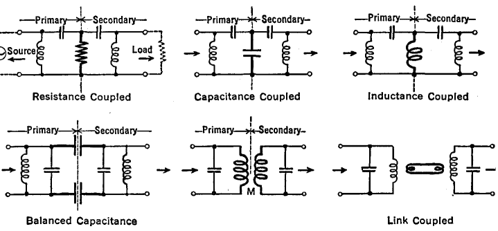
Coupled CircuitsAuthor: J.B. Hoag It is sometimes desirable to transfer electrical energy from one circuit to a neighboring circuit. This can be accomplished, as in Fig. 7 A, by means of a transformer, wherein the source of energy is in the primary circuit and the load is in the secondary circuit. There are other coupling methods which employ a link circuit between the primary and the secondary. In still other types of coupling, the primary and the secondary circuits are actually connected together, using a coil or a condenser or a resistance, as the element common to both primary and secondary circuits.
The coefficient of coupling is defined by the equation,
where the L's are the self-inductances of the primary and secondary circuits. If all of the lines of force from the primary were to cut the secondary, k would be equal to unity; the coefficient would be 100 per cent. This is the " tightest " possible coupling.
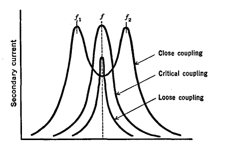
When the circuits are tuned to the same frequency and are so related that but little energy is transferred from the primary to the secondary, they are said to be loose coupled. As the coupling is increased, the secondary increasingly "loads" the primary; and also, the primary increasingly loads the secondary. This loading action broadens the resonance curves of both circuits. At critical coupling, maximum energy is transferred and the resonance curve has quite a broad peak, as in Fig. 7 B. If the circuits are still closer coupled, the energy transferred from one circuit to the other decreases, and the resonance curve will have two peaks, one on either side of the single frequency to which the circuits were originally tuned. The closer the coupling, the greater the frequency separation of these peaks. If the two circuits are not exactly tuned to the same frequency, their effect upon each other is not only to increase the effective resistance (the Q of the circuit decreases) but also to reduce the self-inductance. Hence the peak of the resonance curve shifts to a different frequency.
|
|||||||
Home  Fundamentals Fundamentals  Coupled Circuits Coupled Circuits  Introduction Introduction |
|||||||
Last Update: 2010-11-21


