| Basic Radio is a free introductory textbook on electronics based on tubes. See the editorial for more information.... |

|

Home  Fundamentals Fundamentals  Coupled Circuits Coupled Circuits  Introduction to Filters Introduction to Filters |
||||||


|
||||||
|
Introduction to FiltersAuthor: J.B. Hoag
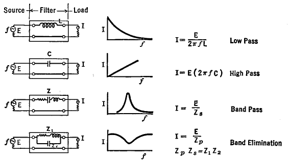
Figure 7 C shows some of the filters with which we are already familiar, together with their curves of output current at different input frequencies, their basic equations, and their names. See also Figs. 5 A and 5 B.
More complicated combinations will serve better in separating neighboring frequencies and in more completely suppressing others. In other words, there are filters which have a sharper cutoff. Of the host of possible LC combinations, a few simplified forms have been developed under the following assumptions and simplifications :
It is possible to describe the characteristic of filters in terms of the output current as in Fig. 7 C, or in terms of the ratio of output to input currents, or the ratio of the output voltage across the load to the input voltage, or the ratio of the power output to the power input, or, as is more common and as we shall now do, in terms of the attenuation of the filter. The attenuation is expressed in decibels and is proportional to the logarithm of the ratio of the output to the input currents or voltages or powers. It is a measure of the losses which take place in the filter at the different frequencies.
|
||||||
Home  Fundamentals Fundamentals  Coupled Circuits Coupled Circuits  Introduction to Filters Introduction to Filters |
||||||
Last Update: 2010-11-21


