| Basic Radio is a free introductory textbook on electronics based on tubes. See the editorial for more information.... |

|

Home  Fundamentals Fundamentals  Radiation Radiation  Field Intensity Field Intensity |
||||


|
||||
|
Field IntensityAuthor: J.B. Hoag The strength or electric field intensity of a radio wave is measured in terms of the e.m.f. (in microvolts, μv.) which it produces between two points 1 meter apart. For example, if 20 micro-volts are generated between the ends of a conductor 1 meter long when the radio wave cuts across it, the field intensity is said to be 20 microvolts per meter (abbreviated μv./m.). If the conductor were 5 meters long, the induced potential would be 100 microvolts.
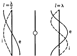
In Fig. 8 C, is shown the idealized case of current i and voltage e along the antenna when it is oscillating at its fundamental frequency or " first harmonic." In figure 8 D, the voltage and current curves are shown for the second mode of vibration. The fundamental wave-length of the antenna is approximately λ= 4 l.
In Fig. 8 D, the h.f. oscillator is located in the center of a straight wire, with the result that the fundamental wave-length is approximately two times its physical length. The Marconi type is more suitable for the longer wave-lengths because it need be only one-half as long as the Hertz type for a given frequency. For higher frequencies (shorter wave-lengths) the Hertz type becomes sufficiently short to be constructed. In addition, it can be mounted far above the earth or other absorbing bodies, whereas the Marconi type uses a ground connection.
|
||||
Home  Fundamentals Fundamentals  Radiation Radiation  Field Intensity Field Intensity |
||||
Last Update: 2010-11-27


