| Basic Radio is a free introductory textbook on electronics based on tubes. See the editorial for more information.... |

|
Home  Basic Circuits Rectifiers Half-Wave Rectifiers Basic Circuits Rectifiers Half-Wave Rectifiers |
||||||


|
  |
|||||
|
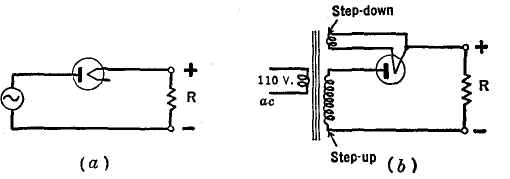
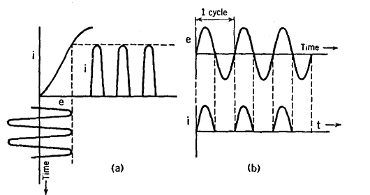
Half-Wave RectifiersAuthor: J.B. Hoag The operation of a half-wave rectifier can be understood from Figs. 11 A and 11 B. The diode is connected in series with the alternating source and the load R. The source may be directly connected to the circuit or its voltage may be stepped up by means of a transformer as in 11 A(b). Whenever the plate is positive with respect to the filament, current flows through the tube and through the load R, in amount determined by the characteristic curve of the tube, shown in Fig. 11 B(a). When the plate is negative, no current flows. Thus, current flows through R each positive half-cycle of the impressed voltage.
The + and — terminals in Fig. 11 A are used in the conventional sense for current flow (through R from + to —), which is reversed from the direction of the electron flow.
The peak-inverse-voltage across the tube in Fig. 11 A (b) is 1.41 times the r.m.s secondary voltage of the transformer (sine wave assumed) . The per cent ripple of a rectifier is defined as 100 times the ratio of the output ripple r.m.s. voltage to the output d.c. voltage. For code transmitters, the ripple may be 5 per cent but for speech transmitters and for receivers it must be less than 0.25 per cent. The ripple frequency in half-wave rectifiers is the same as that of the supply line, i.e., 60 cycles per second for a 60-cycle line.
|
||||||
| Home Basic Circuits Rectifiers Half-Wave Rectifiers |
|
|||||
Last Update: 2009-11-01