| Basic Radio is a free introductory textbook on electronics based on tubes. See the editorial for more information.... |

|
Home  Electronic Devices Multi-Electrode Tubes Some Electron-Multiplier Tubes Electronic Devices Multi-Electrode Tubes Some Electron-Multiplier Tubes |
||||||||
| See also: Secondary Emission, Photo-Multiplier Tubes | ||||||||


|
  |
|||||||
|
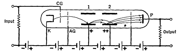
Some Electron Multiplier TubesAuthor: J.B. Hoag The fact that the number of secondary electrons knocked out of a metal plate can exceed the number of incident or primary electrons forms the basis of multiplier tubes. In Fig. 15 G, electrons from the cathode K are controlled by grid C'G and accelerated by the second grid AG. They are directed by electrostatic fields onto the positively charged metal plate 1, where they give rise to secondary electrons. In the figure two secondary electrons are ejected for each primary electron. The secondaries are attracted to the still more positive plate 2, from which four secondaries are ejected. The latter pass to the plate P and to the output. In this case, the current (number of electrons per second) is multiplied fourfold.
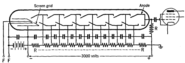
A more practical form of a multiplier circuit is shown in Fig. 15 H, where a single high-voltage supply source (3,000 volts) is used.
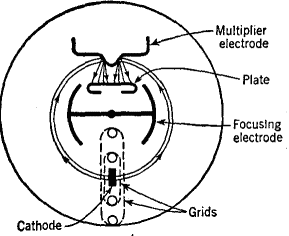
The proper voltages on each multiplier stage are obtained from the potential drop in the series of resistors RR. The absence of coupling stages between one tube and the next makes possible the amplification of a succession of pulses which are very close together, or of very high frequency (microwaves). At the very high frequencies, the time for the electrons to travel from one electrode to another becomes an important fraction of the period of the oscillations. This results in a loss in amplification. The maximum theoretical frequency with present-day tubes is about 2 · 109 cycles per second. In the orbital-beam multiplier tube of Fig. 15 I, the electrons are deflected in a circular path by a positively charged focusing electrode. The tube should prove useful for frequencies of the order of 500 MHz (wave-length = 0.6m).
Further discussion of multiplier tubes will be found in the chapter on photoelectric cells.
|
||||||||
| Home Electronic Devices Multi-Electrode Tubes Some Electron-Multiplier Tubes |
|
|||||||
Last Update: 2009-11-01