| Basic Radio is a free introductory textbook on electronics based on tubes. See the editorial for more information.... |

|

Home  Transmission of Signals Transmission of Signals  The Principle of Amplitude Modulation The Principle of Amplitude Modulation  Grid-Bias Modulation Grid-Bias Modulation |
||||||||
| See also: Plate Modulation, Suppressor-Grid Modulation, Cathode Modulation | ||||||||


|
||||||||
|
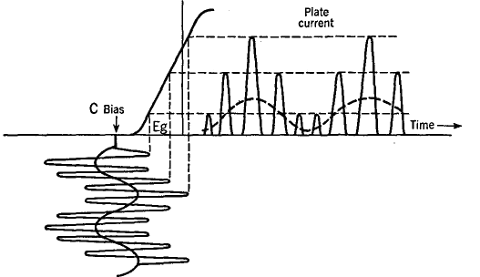
Grid-Bias ModulationAuthor: J.B. Hoag In this method, audio- and radio-frequency voltages are introduced simultaneously into the grid circuit of an amplifier while the B supply remains fixed. The circuit is indicated in Fig. 16 I, with further details in Fig. 16 J.
The output transformer eliminates the d.c. plate current, delivering a modulated carrier voltage to the next amplifier or to the antenna from which the radio wave is radiated. In a way, one might say that the action of the tank circuit and its output coil (Fig. 16 J) is to "straighten the axis" of the plate current (dotted axis in Fig. 16 K). The efficiency of operation of the grid-bias-modulation method is quite low as compared with that of the plate-modulation scheme. On the other hand, the power output of the modulator tube of the grid-bias method need only be one or two watts to operate a modulated tube of considerable power.
|
||||||||
Home  Transmission of Signals Transmission of Signals  The Principle of Amplitude Modulation The Principle of Amplitude Modulation  Grid-Bias Modulation Grid-Bias Modulation |
||||||||
Last Update: 2009-11-01


