Grid-Leak Detectors
Author: J.B. Hoag
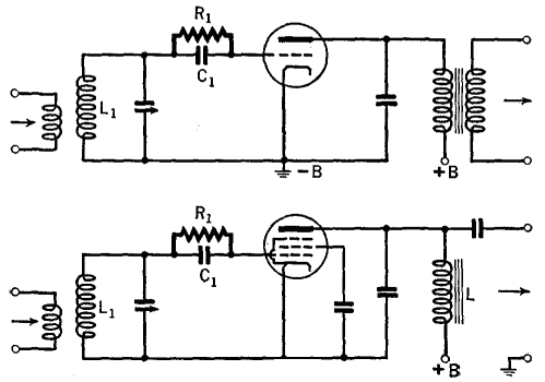
The triode and pentode detectors of Fig. 17 H are equivalent to a combination of a diode rectifier and an a.f. amplifier.
 |
| Fig. 17 H. Grid-leak detector circuits |
The grid acts like the plate of a diode rectifier. The d.c. rectified current flowing through R1 sets up a voltage which serves as the C-bias, while the a.f. currents through this grid-leak set up an a.f. voltage between its ends which is applied to the grid-filament circuit (through coil L1). These a.f. voltages operate the tube like an ordinary amplifier. With triodes, R1 ranges from 1 to 2 megohms, while with pentodes it may be as large as 5 megohms. C1 in both cases ranges from 100 to 250 μfd. In Fig. 17 H, resistance-capacitance coupling can be used at the output, as in Figs. 17 E and 17 G, but transformer and impedance units are shown in order to illustrate the various types of outputs possible in these four circuits. L in Fig. 17 H should be very large, say a 500-henry choke. Circuit constants are the same as in Figs. 17 E and 17 G, except R1 and C1, which are given above.
|


 Transmission of Signals
  The Principle of Detection
  Grid-Leak Detectors


 Transmission of Signals
  The Principle of Detection
  Grid-Leak Detectors

