| Basic Radio is a free introductory textbook on electronics based on tubes. See the editorial for more information.... |
|
Home  Basic Circuits The Operation of Oscilloscopes A Linear Sweep-Circuit Basic Circuits The Operation of Oscilloscopes A Linear Sweep-Circuit |
||||||


|
  |
|||||
|
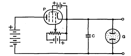
A Linear Sweep-CircuitAuthor: J.B. Hoag In the first place, resistor R of Fig. 22 A is to be replaced by a pentode tube, as shown at P in Fig. 22 G.
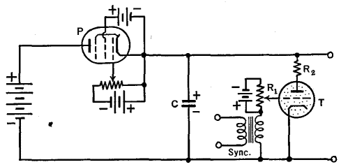
A thyratron may be used in place of the simple glow-tube of the elementary sweep-circuit. As shown in Fig. 22 H, the cathode is connected to the negative side of the condenser and the plate is connected to the positive side.
A negative voltage is applied to the grid of the thyratron and is adjusted by means of the rheostat R1 to such a value that the arc between cathode and plate does not occur until the process of charging the condenser has raised its voltage to the desired striking-potential. When, however, the plate potential has risen to this critical value, the condenser is suddenly discharged through the tube, the voltage on the plate suddenly decreases and, aided by the potential drop across the small resistor R2, becomes zero or even negative. This, of course, shuts off the current and the condenser starts to refill. A simple change of rheostat R1 changes the fixed C-bias of the thyratron and hence the voltage at which the tube starts to conduct. If the grid voltage is small, the charging of the condenser takes only a small time to raise its potential to the point where the thyratron becomes conductive. In this case, the maximum voltage across the condenser will be small, but the frequency of sweeping will be high (or the time for one sweep will be small). On the other hand, if the grid of the thyratron is made more negative, the voltage on the plate must rise to a higher value before the tube will "strike" and discharge the condenser. This means that the amplitude and the time of sweep will both be comparatively large. The ratio of the time to charge and discharge the condenser in the circuit just described can be made as great as 1,000 to 1. Thus the fly-back time will occupy only an insignificant portion of each cycle. This time is primarily determined by that required for the ions in the thyratron to recombine to form neutral particles, i.e., it depends on the de-ionization time of the tube. Stated in a different manner, the maximum frequency of this saw-toothed oscillator cannot exceed that set by the de-ionizing time of the tube. In practice, it is found that the upper limit of satisfactory operation is of the order of 50,000 cycles per second.
|
||||||
| Home Basic Circuits The Operation of Oscilloscopes A Linear Sweep-Circuit |
|
|||||
Last Update: 2009-11-01