| Basic Radio is a free introductory textbook on electronics based on tubes. See the editorial for more information.... |

|

Home  Basic Circuits Basic Circuits  The Operation of Oscilloscopes The Operation of Oscilloscopes  Multiple and Sub-Multiple Linear Sweep Frequencies Multiple and Sub-Multiple Linear Sweep Frequencies |
||||||||


|
||||||||
|
Multiple and Sub-Multiple Linear Sweep FrequenciesAuthor: J.B. Hoag
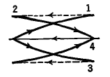
If the sweep-frequency is still further increased so that the time represented from the left to the right of the screen is only one-quarter of the a.c. period, then the pattern will appear as in Fig. 22 N.
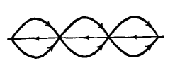
In case the sweep and alternating potentials have a frequency ratio of 3 to 2, the pattern will appear as in Fig. 22 0.
From this discussion it should be obvious that, by observation of the stationary patterns on the screen, it is possible to calibrate the sweep-frequency against a standard alternating frequency such as the 60-cycle line. Actually, this calibration proves to be satisfactory only when the ratio of the two frequencies is not too great. After the calibration of the sweep-frequency, the process may be reversed to determine an unknown frequency applied to the vertical deflecting plates. However, it is difficult to build sweep-circuits in which the frequency is always the same for a given adjustment of the circuit constants. In the case of the circuit of Fig. 22 H, the striking-potential of the thyra-tron varies slightly with the temperature of the tube.
|
||||||||
Home  Basic Circuits Basic Circuits  The Operation of Oscilloscopes The Operation of Oscilloscopes  Multiple and Sub-Multiple Linear Sweep Frequencies Multiple and Sub-Multiple Linear Sweep Frequencies |
||||||||
Last Update: 2009-11-01


