| Basic Radio is a free introductory textbook on electronics based on tubes. See the editorial for more information.... |

|

Home  Amplifiers Amplifiers  Class A, B, and C Amplifiers Class A, B, and C Amplifiers  Linear and Non-Linear Circuit Elements Linear and Non-Linear Circuit Elements |
||||||||||||||||||


|
||||||||||||||||||
|
Linear and Non-Linear Circuit ElementsAuthor: J.B. Hoag
If the "circuit elements" in the box consist merely of a series resistance, the symmetrical straight line of Fig. 23 A will be obtained.
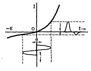
Let a fluctuating voltage (e-t) be applied to the input terminals. Then the fluctuating output current (i-t), as shown in this figure, will have the same shape as that of the input voltage. If the circuit elements consist of crystals, such as galena or iron pyrites, or if they consist of copper-oxide rectifiers, the unsymmetrical, non-linear (= non-ohmic) curve of Fig. 23 B will be obtained.
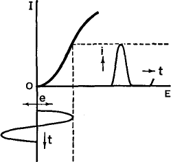
A pure sinusoidal voltage at the input will not yield an output current of the same (sinusoidal) wave-form. Instead, the current will be partially rectified, as shown in the figure, and will be distorted or "full of harmonics". If the box contains a diode, the detector or rectifier property shown in Fig. 23 C will result.
These conditions were discussed in some detail in earlier chapters. The rectifying action of a triode operating on the upper knee of its characteristic curve is shown in Fig. 23 D.
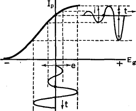
Figure 23 E shows the output currents versus input grid voltages of triodes operated from a point in the middle of the straight portion of the characteristic curve. Notice that when too great an input voltage is used, the upper and lower knees of the characteristic curve are in use and the tops and bottoms of the output current are "squared off".
This principle is undesirable in some applications, such as amplifiers, where it is called distortion, but it is useful in other applications, such as current-limiting devices and square-wave generators. When the grid of a triode is made quite positive, it diverts considerable numbers of electrons to itself. Then the plate current falls off, as indicated by the drop in the upper end of the curve in Fig. 23 F.
An extremely large grid voltage fluctuation gives rise to the peculiar dip in the top of the square wave.
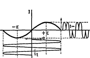
Figure 23 G shows the output current versus input voltage for an electrical device called a "thyrite bridge circuit". Note that the output has a double hump, or frequency, for each half-cycle of the applied voltage.
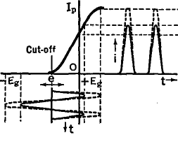
Figure 23 H shows the characteristic curve of an ordinary triode whose C-bias is so negative that the operating point is located at the cutoff point, i.e., for Class B amplification. The output current in this case is rectified. Class C amplifiers are operated with the C-bias well to the left of the cutoff point.
|
||||||||||||||||||
Home  Amplifiers Amplifiers  Class A, B, and C Amplifiers Class A, B, and C Amplifiers  Linear and Non-Linear Circuit Elements Linear and Non-Linear Circuit Elements |
||||||||||||||||||
Last Update: 2009-11-01


