Direct Current Amplifiers
Author: J.B. Hoag
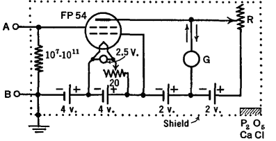
There are numerous cases in which small electrical currents and voltages must be amplified before they can operate relays, rugged meters, mechanical counters, or other devices. In some cases, the currents and voltages are of a pulse, an audio, or a radio frequency nature and can be amplified by circuits containing condensers and coils; but there are others where the currents flow in but one direction. For these cases a direct current amplifier must be used. A simple d.c. amplifier would consist of a single tube with a resistance input and with the "load" (device to be operated) in the plate circuit. However, the d.c. plate current is so large in such a case that it often overshadows the small change caused by a small input voltage. In order to "balance-out" the d.c. plate current, various circuits have been devised. One of these is shown in Fig. 24 A.
 |
| Fig. 24 A. A simple d.c. amplifier |
A special tube is shown which has an unusually small leakage of current between its input grid and cathode. This permits the use of a very high input resistor, from 107 to 1011 ohms. Then, when a very small voltage is applied, the drop across this resistance is sufficiently large as to cause a considerable change in the plate current over and above its d.c. value. The galvanometer G in the plate circuit is a current-measuring instrument which will respond to currents as small as one one-billionth of an ampere; it would be badly damaged by the d.c. plate current alone. Hence, in the absence of an input voltage, the plate current is "balanced-out" by-means of the battery in the lower right-hand corner of the figure. This battery sends a current through the adjusting resistance R and the galvanometer, in the opposite direction to the plate current of the tube. In other words, when R has been properly adjusted, there will be no current flow through G. Now, when a signal makes the grid of the tube positive, the plate current will increase by a certain amount. This increase causes a flow through the galvanometer and hence a deflection of its moving part; which may be observed and measured. The circuit can be calibrated so that the deflections of the galvanometer give a direct measure of the strength of the input voltage. If the value of the grid resistance is known, the deflection is a measure of the small current sent into the amplifier. Currents as small as 10-17 ampere have been measured with improved forms of this amplifier.
|


 Amplifiers
  Direct Current Amplifiers
  Direct Current Amplifiers


 Amplifiers
  Direct Current Amplifiers
  Direct Current Amplifiers

