| Basic Radio is a free introductory textbook on electronics based on tubes. See the editorial for more information.... |

|

Home  Amplifiers Amplifiers  Feedback Amplifiers Feedback Amplifiers  A Selective Circuit A Selective Circuit |
||||||||||||


|
||||||||||||
|
A Selective CircuitAuthor: J.B. Hoag
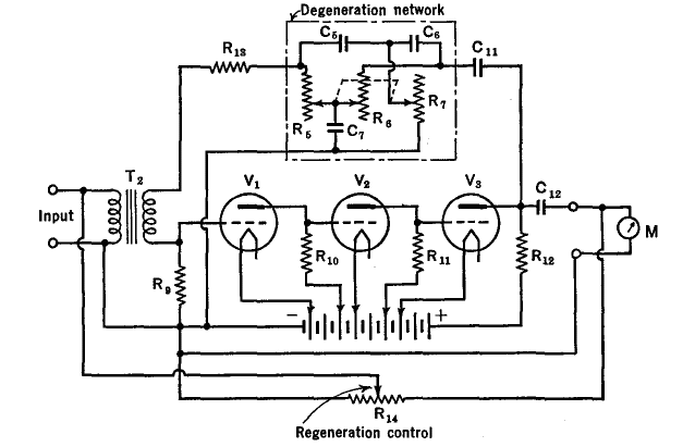
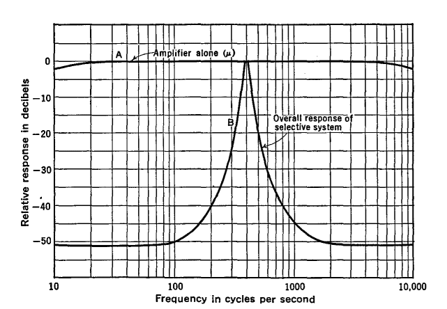
Figure 26 K shows a circuit with a degenerative network whose frequency response has a selective peak, as in Fig. 26 L.
By changing the values of R5, R6, and R7 (with a single knob), the peak of curve B in Fig. 26 L can be shifted to the various frequencies throughout the range of the amplifier, without changing the relative sharpness of the curve.2
When the regenerative feedback of Fig. 26 K is added, the circuit can be made to oscillate at a frequency determined chiefly by its selectivity curve. An unusually pure sine wave is generated by this simple circuit.
|
||||||||||||
Home  Amplifiers Amplifiers  Feedback Amplifiers Feedback Amplifiers  A Selective Circuit A Selective Circuit |
||||||||||||
Last Update: 2010-11-21


