| Basic Radio is a free introductory textbook on electronics based on tubes. See the editorial for more information.... |

|

Home  Amplifiers Amplifiers  R.F. and I.F. Amplifiers R.F. and I.F. Amplifiers  R.F. Class C Power Amplifiers R.F. Class C Power Amplifiers |
||||||


|
||||||
|
R.F. Class C Power AmplifiersAuthor: J.B. Hoag
Improper adjustment, however, can result in very low efficiency. It has been found that optimum conditions exist when the plate current flows from 33 to 47 per cent of the time of one cycle. This means that, of the total of 360° corresponding to one cycle, the grid voltage reaches and remains above the cutoff point for 120° to 150°, as shown in Fig. 27 J.
For 120°, the r.f. grid voltage reaches 50 per cent of its peak value at cutoff, and for 150°, it reaches 25 per cent at cutoff. The correct C-bias is therefore equal to the cutoff plus 25 to 50 per cent of the peak r.f. grid voltage. Because power is consumed in the grid circuit (and to allow for contingencies), the "driver" or input source should be designed to give an amount of power equal to two or three times the expected grid-circuit losses. This is particularly true at the ultra-high frequencies where the losses occur not only in the wires themselves but also in the dielectric of the glass envelope of the tube. The plate circuit of an r.f. Class C amplifier contains a resonant circuit, as at LC in Fig. 27 G. When tuned to the frequency of the input signal, this circuit acts like a pure resistance whose value, including the reflected impedance of the output load, is usually of the order of a few thousand ohms. The more power delivered by the amplifier to the output circuit (say the antenna of a transmitter), the lower this resistance, and vice versa. For good efficiency this resistance should be relatively high. Its best value is such that the maximum r.f. grid voltage is equal to the minimum instantaneous plate voltage.
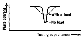
The direct pulsating plate current shown on the right of Fig. 27 J causes the tank circuit currents to oscillate back and forth, transfer ring energy alternately from the condenser to the coil and back again in the usual fashion. The periodic (and properly timed or resonated) pulses of plate current make up for the circuit and load losses so as to keep the circuit in oscillation. The fluctuating magnetic field of coil L cuts the turns of wire in the output coil (see Fig. 27 G) to set up an e.m.f. and to drive a current in the output circuit. It is desired that the wave-form of this output should be a replica of that applied to the grid of the amplifier, and hence be free of distortion or harmonic content. This is not possible; yet the harmonic content will be reasonably low when the Q (= 2πfL/R) of the tank circuit is high. Transmitting coils, which largely determine the Q of the tank circuit, usually have a Q ranging from one hundred to several hundred, with no load, but drop to much lower values when power is drawn from the amplifier, due to the reflected impedance. This change with load can be shown in terms of the sharpness of resonance as in Fig. 27 K. The Q of the tank circuit should be 12 or higher.
|
||||||
Home  Amplifiers Amplifiers  R.F. and I.F. Amplifiers R.F. and I.F. Amplifiers  R.F. Class C Power Amplifiers R.F. Class C Power Amplifiers |
||||||
Last Update: 2010-11-27


