| Basic Radio is a free introductory textbook on electronics based on tubes. See the editorial for more information.... |

|

Home  Transmission of Signals Transmission of Signals  The Modulation of R.F. Amplifiers The Modulation of R.F. Amplifiers  Plate Modulation Plate Modulation |
||||


|
||||
|
Plate ModulationAuthor: J.B. Hoag
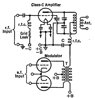
Figure 28 A shows the circuit of a Class C amplifier with plate modulation from a Class B modulator. In the design of " plate-modulated " r.f. amplifiers we are concerned with the following problems: (1) that the modulation shall be as nearly 100 per cent as possible, (2) that the output audio wave-form shall be as nearly a replica of the a.f. sound input to the microphone as possible, (3) that the power output for a given set of tubes in the circuit shall be as great as possible.
Some of the details of the circuit in Fig. 28 A are given in the following paragraphs. The tube manufacturer usually supplies data on the proper grid bias and grid current for the Class C modulated tube. A well-filtered C-battery supply, having good regulation, should be used to bias the grid to cutoff; and this should be supplemented by the voltage drop in the grid leak so as to make the total grid voltage between two and three times the cutoff value. If triodes are used, as in Fig. 28 A, the neutralization of the amplifier must be very nearly perfect. The voltage of the r.f. driver ahead of the modulated tube should be sufficient to drive the grid of this tube somewhat positive during its peak positive half-cycle, and its power should be two or three times greater than that which is normally consumed in the grid circuit. The plate bypass condenser, C of Fig. 28 A, must have a high reactance for audio frequencies in order to provide tube safety and good modulation. Values less than 0.002 μfd. are satisfactory. The output peak voltage of the modulator must be such that the a.f. voltage on the plate of the amplifier tube is equal to the d.c. plate voltage if 100 per cent modulation is to be obtained. Then the r.f. output will fluctuate between twice the unmodulated r.f. voltage and zero. If the audio signal is a pure sine wave, the modulator must furnish an amount of power equal to 50 per cent of the d.c. plate power put into the amplifier stage. Thus, if the amplifier is rated at 1,000 watts input, it is necessary that the audio amplifier put out 500 watts. For complex speech waves the average power of the modulator need be only one-half of the former figure, but its instantaneous power output must still be the same as for the pure sine wave. In order to adjust the circuits for the above stated conditions (which yield 100 per cent modulation), the load on the amplifier is varied until the product of the d.c. plate voltage and the d.c. plate current is of the desired value. Keep the tank circuit tuned to resonance while changing the load. When the amplifier is properly adjusted, the d.c. plate currents will be the same with or without modulation.
|
||||
Home  Transmission of Signals Transmission of Signals  The Modulation of R.F. Amplifiers The Modulation of R.F. Amplifiers  Plate Modulation Plate Modulation |
||||
Last Update: 2009-11-01


