| Basic Radio is a free introductory textbook on electronics based on tubes. See the editorial for more information.... |

|

Home  Oscillators Oscillators  Crystal Oscillators Crystal Oscillators |
||||||||
| See also: Crystals for Oscillators | ||||||||


|
||||||||
|
Crystal OscillatorsAuthor: J.B. Hoag
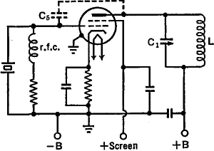
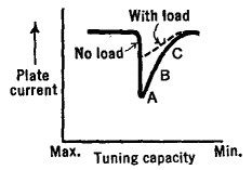
In order to adjust a crystal oscillator, a d.c. milliammeter is connected in series with the plate supply. The tuning condenser C1 (Fig. 29 E) is then varied until the plate current dips as in Fig. 29 F.
Maximum power is developed at the point A, but it is best to operate somewhere between B and C, where the oscillator is more stable and the crystal current is smaller. The dotted curve of Fig. 29 F is for the case when the oscillator is delivering power. The dip will be less pronounced the greater the load. The crystal current, and hence its heating, the cause of breakdown, will be less when the oscillator is loaded, than when it is unloaded.
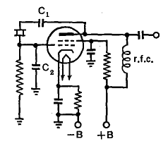
Figure 29 G shows another type of quartz-crystal oscillator which does not require tuning control. It is the equivalent of the ultraudion circuit, with the tuned circuit replaced by the crystal; or of a Colpitts oscillator with the crystal displacing the tank coil inductance. Condensers C1 and C2 are in series with the crystal, from the plate to the cathode. Hence these condensers determine the feedback. As tuned tanks are not used in this simple circuit, a wide range of frequencies, one for each crystal used, can be obtained without serious change in the circuit values. The circuit is limited to low power outputs, and must be carefully adjusted to avoid damaging the crystal.
|
||||||||
Home  Oscillators Oscillators  Crystal Oscillators Crystal Oscillators |
||||||||
Last Update: 2009-11-01


