| Basic Radio is a free introductory textbook on electronics based on tubes. See the editorial for more information.... |

|

Home  Oscillators Oscillators  Beat-Frequency Oscillators Beat-Frequency Oscillators |
||||||


|
||||||
|
Beat-Frequency OscillatorsAuthor: J.B. Hoag
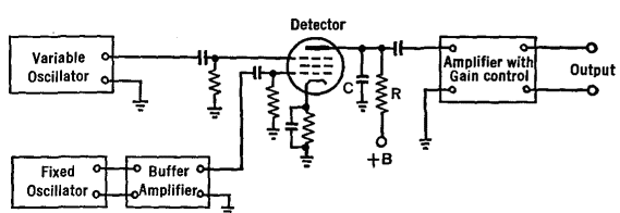
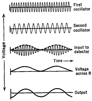
Suppose the frequency of the fixed oscillator of Fig. 29 I were established at 200,000 cycles per second, while that of the variable oscillator was changed (by varying its tank condenser) from 200,000 to 210,000 cycles per second. Then the beat-frequency heard in a loudspeaker connected to the output terminals would change from zero to 10,000. Thus, with a single dial control on the condenser of the variable oscillator, the entire audio band can be covered. When the two oscillators have nearly the same frequency, they tend to " pull-in," the stronger one forcing the weaker one to assume its frequency. This tendency can be overcome by use of a buffer-amplifier (which is just like any other amplifier covering the proper frequency range) and by injecting the two oscillator voltages into the detector on two separate grids, with a screen grid between, as indicated in Fig 29 I The production of beats is referred to as a heterodyne process. Hetero means to mix and dyne is a unit of force; hence — a mixture of the outputs of the two oscillators. Suppose the fixed frequency was 1,000,000, and the other frequency was 1,000,401 cycles per second. The beat-note would have a frequency of 401 cycles per second. Let this be beat a second time against a 400-cycle oscillator. The second beat-note would be 1 cycle per second. Now change the variable oscillator by only one part in a million, to 1,000,402. The second-beat would change from 1 to 2 cycles per second, a very noticeable difference. It does not require a very large change in the capacitance of an oscillator to shift its frequency by this small amount. If the plates are moved closer together by one one-millionth of an inch, the change can be detected. Any other shift in the variable oscillator, in its capacitance, resistance, inductance, or voltages can be observed with equal delicacy.
|
||||||
Home  Oscillators Oscillators  Beat-Frequency Oscillators Beat-Frequency Oscillators |
||||||
Last Update: 2009-11-01


