| Basic Radio is a free introductory textbook on electronics based on tubes. See the editorial for more information.... |

|

Home  Some Special Circuits Some Special Circuits  Square Waves Produced by Clipper Action Square Waves Produced by Clipper Action |
||||||||


|
||||||||
|
Square Waves Produced by Clipper ActionAuthor: J.B. Hoag Suppose a comparatively large sinusoidal voltage is applied to the grid of an amplifier tube. When the grid goes negative beyond the cutoff point, plate current ceases to flow and the bottoms of the sine curve are clipped or squared off. When the grid goes positive to the saturation region beyond the upper knee of the characteristic curve, the plate current is limited and the tops of the sine curve are clipped off. When sharp cutoff tubes are used, the bottoms of the sine waves are squared off with reasonable sharpness. On the other hand, the tops of the waves are not sharply squared off because of the grid current which flows when the grid goes positive and extracts electrons from the plate circuit, as well as develops a C-bias across the input resistors.
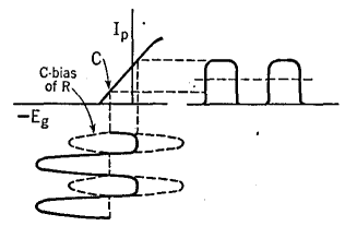
During the negative half-cycles, electrons on the grid condenser, C of Fig. 30 A, flow to ground through resistor R1 and develop a C-bias of essentially constant amount, as indicated at C in Fig. 30 B. The constancy is due to the fact that the discharge time of C through R1 (0.1 sec.) is large compared with the period of the input voltage. When the grid of tube 1, Fig. 30 A, goes positive, its plate current rises, the upper end of R2 becomes more negative, and this voltage change feeds through C2 to the grid of tube 2. In other words, there is a phase reversal of 180° between the plate current of 1 and the grid voltage of 2. The time it takes to discharge C2 through the grid leak of the second tube is chosen quite long so that a comparatively fixed and large C-bias is established on 2, as indicated in Fig. 30 C.
Its value is controlled by the strength of the input voltage and is such that the positive peaks just drive the grid of 2 slightly positive. Note, in Fig. 30 C, that only the square bottoms of the plate current of the first tube are used to give plate current in tube 2. Hence both the tops and bottoms of the current through R3 are sharply square. Note, also, that the time constant of the output circuit is very large, so as to retain this squareness.
|
||||||||
Home  Some Special Circuits Some Special Circuits  Square Waves Produced by Clipper Action Square Waves Produced by Clipper Action |
||||||||
Last Update: 2009-11-01


