| Basic Radio is a free introductory textbook on electronics based on tubes. See the editorial for more information.... |

|

Home  Some Special Circuits Some Special Circuits  A Circuit to Convert Random Pulses into Uniform Pulses A Circuit to Convert Random Pulses into Uniform Pulses |
||||


|
||||
|
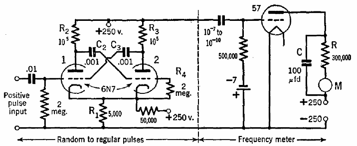
A Circuit to Convert Random Pulses into Uniform PulsesAuthor: J.B. Hoag The left half of the circuit of Fig. 30 I will convert random pulses of from 30 to 3,000 counts per minute into pulses of uniform length and amplitude.
Thus an input pulse of any size or duration (within limits) initiates a series of events wherein 2 is turned off and then back on again sharply after a definite time interval determined by the circuit constants and not by the input pulse. The resultant potential variations across R3, and across the output terminals shown in Fig. 30 I, are of square wave-form.
|
||||
Home  Some Special Circuits Some Special Circuits  A Circuit to Convert Random Pulses into Uniform Pulses A Circuit to Convert Random Pulses into Uniform Pulses |
||||
Last Update: 2009-11-01


