| Basic Radio is a free introductory textbook on electronics based on tubes. See the editorial for more information.... |

|

Home  Some Special Circuits Some Special Circuits  Electronic Switches Electronic Switches |
||||||||||
| See also: The Multivibrator Oscillator | ||||||||||


|
||||||||||
|
Electronic SwitchesAuthor: J.B. Hoag
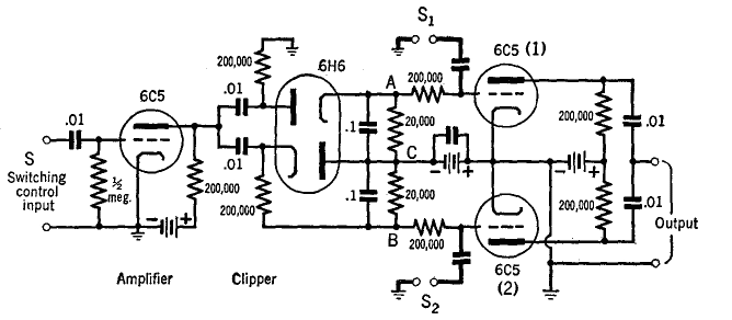
The circuit diagram of a particular electronic switch is shown in Fig. 30 N.
A sinusoidal wave applied at S is amplified and then clipped by the twin diode 6H6. Thus positive half-cycle square-waves appear across AC and negative half-cycle square-waves across BC. The 6C5 tubes on the right are biased at or beyond cutoff. When the input from 6H6 makes 1 conductive, a signal at S1 will pass on to the output terminals. When the input from 6H6 makes 2 conductive, a second signal at S2 will go to the output but, since 1 is non-conducting at this time, the signal at S1 does not go out. Thus, signals at S1 and S2 are passed on, alternately, and at a rate of succession determined by the frequency of the switching control S. In other electronic switches,1 multi-grid tubes are used instead of the 6C5 tubes at the right of Fig. 30 N, so that the input signals from S1 and S2 can be injected on separate grids from those which un-bias the tubes. Also, a multivibrator circuit is sometimes used instead of the clipper-tube to generate the square-waves for un-biasing the switching tubes.
|
||||||||||
Home  Some Special Circuits Some Special Circuits  Electronic Switches Electronic Switches |
||||||||||
Last Update: 2010-11-21


