| Basic Radio is a free introductory textbook on electronics based on tubes. See the editorial for more information.... |

|
Home  Some Special Circuits Voltage Stabilizers Some Special Circuits Voltage Stabilizers |
||||||||


|
  |
|||||||
|
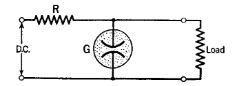
Voltage StabilizersAuthor: J.B. Hoag There are many cases in receivers and transmitters where it is necessary that the voltage of the power supply unit remain constant even though large changes occur in its output load or in its input voltage. For small voltages and currents, glow-tubes may be used, as in Fig. 30 P.
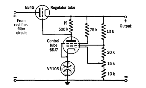
Figure 30 Q shows a circuit which will stabilize at 300 volts to within 1 volt for line or load changes of 25 per cent. The regulator tube acts like a series resistor. Its resistance is changed by the grid-bias change developed across R by the plate current of the control tube. In turn, the change of resistance of the regulator tube changes the voltage across the control tube and hence its plate current. Thus, if the voltage at the top of R should increase, the bias voltage and the internal resistance of the regulator tube will be increased and the voltage at the top of R will return to its proper value. The remainder of the circuit serves to apply the proper voltages to the grids of the 6SJ7 tube to assist in the stabilizing action. The constant voltage drop across the VR 105 glow-tube maintains the cathode of the control tube at a fixed voltage above ground. The grid current of a tube flows, in the conventional sense, from the grid to the cathode. Hence, the current flow from a C-bias pack is in the reverse direction to that from a B power supply.
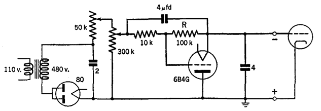
In the circuit of Fig. 30 R, the grid current through resistor R makes the grid of the regulator tube 6B4G go positive, which lowers its internal resistance. Thus the regulator tube acts as a variable bleeder resistance across the output of the rectifier circuit and automatically maintains a constant output voltage. In the circuit shown, changes of the 300,000-ohm resistor (rough adjustment), and the 50,000-ohm resistor (fine adjustment) , give voltages from 100 to 600. The maximum grid currents permissible for these voltages are 100 ma. and 25 ma., respectively.
|
||||||||
| Home Some Special Circuits Voltage Stabilizers |
|
|||||||
Last Update: 2009-11-01