| Basic Radio is a free introductory textbook on electronics based on tubes. See the editorial for more information.... |

|

Home  Transmission of Signals Transmission of Signals  Receivers Receivers  Alignment Methods Alignment Methods |
||||||


|
||||||
|
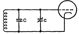
Alignment MethodsAuthor: J.B. Hoag In order to operate several stages of tuned r.f. amplifiers, with a single control, the tuning condensers are mechanically coupled together. Often these "ganged" condensers are all mounted on a common shaft. It is necessary that, as the control knob is turned, the various stages shall all "track" or tune to the same radio frequency at every position on the knob's scale. When this is true, the circuits are said to be "tracking" each other. In order that this shall be possible, the coils must be as nearly identical as possible and the capacity of the individual condensers in the gang must all increase at the same rate as the knob is rotated. Even so, the circuits may not track because of differences at the zero setting of the condensers, where the small capacities are not all the same. These differences are adjusted by connecting trimmer condensers of comparatively small capacity c in parallel with the main tuning condenser C, as in Fig. 32 L.
In the case of a superhet, it is also necessary that the frequency of the local oscillator be changed simultaneously and by such an amount that the beat or intermediate frequency shall always be of a fixed amount regardless of the signal frequency.
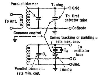
Figure 32 M shows a typical converter circuit with its padding condensers C5. In this combination, C5 consists of a small fixed condenser paralleled by a still smaller variable condenser. The trimmer condenser C4 is first adjusted at the high-frequency end of the tuning range so as to deliver the correct i.f. (maximum output). The low-frequency end is then adjusted by means of C5 to give the same i.f. (maximum output). When a receiver has to cover a wide range of frequencies, the tuning coils are changed either by means of a switch or by a plug-in arrangement. For ease of tuning with a given coil, it is desirable that one rotation of the condenser should cover a definite band of frequencies. In order to spread these frequencies out over the entire dial of the condenser, small trimmer and/or padding condensers are used. For the i.f. alignment:
The usual alignment sequence is: (1) i.f., (2) local oscillator, (3) mixer, (4) r.f. But differing sequences are used by different operators.
|
||||||
Home  Transmission of Signals Transmission of Signals  Receivers Receivers  Alignment Methods Alignment Methods |
||||||
Last Update: 2011-03-27


