| Basic Radio is a free introductory textbook on electronics based on tubes. See the editorial for more information.... |

|

Home  Transmission of Signals Transmission of Signals  Receivers Receivers  Some Special Features of Receivers Some Special Features of Receivers |
|||||||||||


|
|||||||||||
|
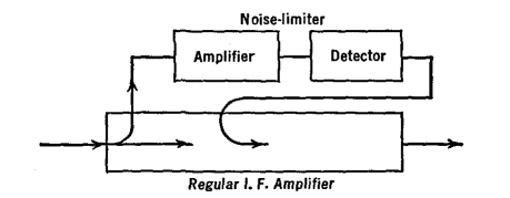
Some Special Features of ReceiversAuthor: J.B. Hoag Noise-limiters are used to suppress strong impulses of short duration, such as those from sparking contacts and atmospheric static. In one circuit, Fig. 32 Q, a part of the i.f. is diverted along a path paralleling the regular i.f. amplifier.
It reaches a detector tube which has been heavily biased; so much so that the i.f. signal in this path stops at this point. If, however, a sudden sharp pulse raises the detector tube above cutoff, the pulse passes through and is fed back in reverse phase to block the pulse which tries to carry through the regular i.f. amplifier.
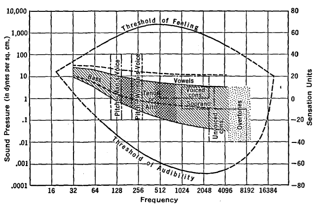
The human ear has a peculiar response to just barely audible sounds of different pitches. It is found that more energy must be used at low or at high frequencies than at intermediate values if the threshold of hearing is to be reached. See Fig. 32 R. A series condenser and inductance are shunted across part of the gain control of a receiver, and adjusted for resonance at approximately 1,000 cycles per second, where the ear has a low threshold. Then the audio frequencies in this intermediate region are bypassed more than those at the higher and lower ends. This is called compensated volume control.
A variable resistance and a fixed condenser tied across the primary of the output or speaker transformer can be used to emphasize the low-or the high-pitched sounds. This is called a tone control system.
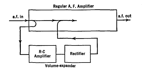
A receiver can have automatic tuning such that by pushing a button, a mechanical system, sometimes a motor, moves the tuning condensers to their proper positions for the reception of a desired station. It is desirable to increase the loudness of the loud sounds and to soften the weak ones, especially in phonograph amplifiers. Automatic-volume expanders have been developed for this purpose. Their operation can be understood from Fig. 32 S.
Part of the a.f. at the input end of a regular audio amplifier is diverted to the volume expander where it is amplified and rectified. The output voltage is greater if the a.f. is of greater strength, and vice versa. This is fed back to the regular amplifier (via one of the grids of a multi-grid tube) in such phase as to aid the regular signals. In this way loud signals are aided a great deal, while soft sounds are only increased by a comparatively small amount. In order to keep the intermediate frequency of a superhet centered on its band, automatic-frequency control (a.f.c.) is used. This is very useful to compensate for frequency changes in the local oscillator, and especially with circuits which have automatic tuning. Details of its operation can only be understood after studying the chapter on Frequency Modulation, but the principle can be learned from Fig. 32 T.
If the i.f. shifts off the center of its band, the " discriminator " (a rectifier) turns the frequency change into a proportionate voltage change. This voltage is fed to a tube in the " frequency control" which, together with a condenser and resistor across the tank circuit of the local oscillator, changes the reactance (but not the resistance) of the tank and hence the frequency of the local oscillator. When properly adjusted, any shift in the i.f. is applied through the a.f.c. circuit so as to bring the local oscillator frequency to just the correct value to re-establish the i.f. on the center of its channel.
|
|||||||||||
Home  Transmission of Signals Transmission of Signals  Receivers Receivers  Some Special Features of Receivers Some Special Features of Receivers |
|||||||||||
Last Update: 2011-03-27


