| Basic Radio is a free introductory textbook on electronics based on tubes. See the editorial for more information.... |

|

Home  Transmission of Signals Transmission of Signals  Frequency Modulation Frequency Modulation  A Reactance Modulator A Reactance Modulator |
|||||||


|
|||||||
|
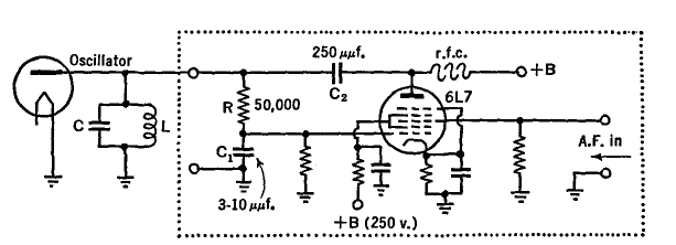
A Reactance ModulatorAuthor: J.B. Hoag A reactance modulator changes the frequency of the tank circuit of the oscillator by changing its reactance. This is accomplished by a combination of a resistor, a condenser, and a vacuum tube (the modulator) connected across the tank circuit of the oscillator as in Fig. 33 A, and so adjusted as to act as a variable inductance or capacitance.
The net result is to change the resonant frequency of the LC circuit by amounts proportional to the instantaneous a.f. voltages applied to the grid of the modulator tube, without changing the resistance of the LC circuit or the amplitude of the oscillations. A modulator circuit is shown in Fig. 33 B.
The voltages supplied to both the modulator and oscillator must be carefully stabilized to prevent undesired frequency changes. The speech amplifier (Fig. 33 A) does not have to deliver any power and need supply only a small output voltage, say 10 or 15 volts. A pentode and triode, R-C coupled, will be sufficient even with a sensitive microphone and a high-powered oscillator. The frequency change of LC per volt change on the a.f. grid of the modulator tube will be greater when C1,Fig. 33 B, is made smaller. The blocking condenser C2 has a comparatively high value, and hence offers but small reactance to r.f. currents.
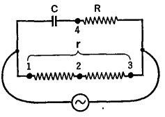
In Fig. 33 B, the radio-frequency voltages which are developed across the tank in the oscillator circuit also appear across the RC1 circuit and across the parallel 6L7 modulator tube. Now look up the phase-shifting circuit of Fig. 19 H. The resistance r has been replaced by the internal resistance of the modulator tube of Fig. 33 B. The voltage drop across C1 is 90° out of phase with the tank voltage. It is applied to the control grid of the 6L7 whose r.f. plate current responds in the same phase. Thus this current is made to lag 90° behind the tank voltage. The r.f. plate current flows through the tank circuit and, combined with the current therein, is equivalent to a new current whose phase differs from the normal value just as though an additional reactance (not resistance) had been connected in with L and C. This, of course, changes the frequency of the LC circuit and hence of the transmitter. When a.f. is fed into the modulator tube, it causes proportionate changes in the r.f. plate current and hence in the equivalent reactance of the LC circuit.
|
|||||||
Home  Transmission of Signals Transmission of Signals  Frequency Modulation Frequency Modulation  A Reactance Modulator A Reactance Modulator |
|||||||
Last Update: 2009-11-01


