| Basic Radio is a free introductory textbook on electronics based on tubes. See the editorial for more information.... |

|

Home  Microwaves Microwaves  The Magnetron Oscillator The Magnetron Oscillator |
|||||||||
| See also: The Magnetron | |||||||||


|
|||||||||
|
The Magnetron OscillatorAuthor: J.B. Hoag
The wave-length which will be generated can be predicted from the following equation:
where λ is the wave-length in centimeters and Hc is the field strength in oersteds. This is only an approximate equation, the constants ranging from 10,000 to 16,000, according to the temperature of the filament. Figure 38 F shows a split-anode magnetron.
The shaded area represents a tuned circuit. This can be sufficiently small for the short waves generated that it can be built right inside the vacuum tube. With the split-anode type of magnetron, the tuned circuit interacts upon the electrons in such a way that they move along a spiral trajectory, as indicated at the right of the figure. Magnetrons with three, four, five, and six slits have been constructed. The three-slit magnetrons have been used to produce three-phase high frequency currents. The electrons which return toward the filament often bombard it with sufficient energy to raise its temperature appreciably and cause the emission of a larger number of new electrons. Thus, just at the beginning of the cutoff, the plate current can be made to rise in the manner shown at (b) in Fig. 38 G.
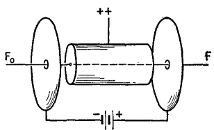
The intensity of the oscillations becomes increasingly great from (a) toward (b) but so does the danger of burning out the filament. Hence in practice, the tubes are generally operated at a point just to the right of (a). The intensity of the oscillations can be increased very much, either by tilting the axis of the tube to about 5° from the direction of the magnetic lines of force, or by the addition of end-plates. An end-plate magnetron is shown in Fig. 38 H, where it will be observed that one of the end-plates is positive and the other negative.
The electric field between the end-plates causes the electrons to move axially while they are executing their customary circular motions. This is the same net result as produced by tilting a simple tube in the magnetic field. Apparently, for maximum radio frequency output, the electrons must not be allowed to accumulate around the filament after their excursions to the plate and back. A more advanced magnetron has been built in which the end-plates were divided up into a number of segments. Then, as the electrons rotated in their orbits while approaching the end-plates, they induced charges on the segments. The resultant u.h.f. potentials are built up to considerable magnitude by-attaching linear circuits to the segments. The place of the magnetron in the present-day picture of microwaves can be simply summarized as follows: the tube will produce the shortest known wave-lengths, but, because of the necessary high voltages and strong magnetic fields, it is a comparatively heavy and cumbersome unit.
|
|||||||||
Home  Microwaves Microwaves  The Magnetron Oscillator The Magnetron Oscillator |
|||||||||
Last Update: 2010-11-27


