| Electronic Transformers and Circuits is a free introductory textbook on transformers and related circuits. See the editorial for more information.... |

|

Home  Transformer Construction, Materials, and Ratings Transformer Construction, Materials, and Ratings  Creepage Distance Creepage Distance |
||||||||
| See also: Dielectric Strength, Impregnation | ||||||||


|
||||||||
Creepage Distance
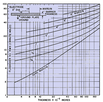
This is especially helpful when the part of the coil adjacent to the core tongue is at low potential and the upper part is at high potential, as in some plate transformers. When the whole coil is at high potential it may be insulated by taping the coil, but taping is expensive and is avoided wherever creepage safely provides the necessary insulation strength. Creepage distances over treated cloth or other organic material in air are shown in Fig. 40 for breakdown voltages up to 100 kv.
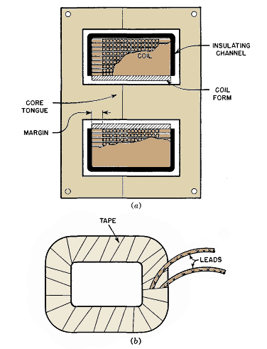
The primary purpose of these curves is to find the proper margins for coils adjacent to the core. Insulation between the start (or finish) turn of the first layer and the core consists of creepage along the margin plus the thickness of the coil form. This is not a relevant distance, however, if the coil lead is brought across the margin and up the side of the coil. In such a case, the only creepage distance is the thickness of the coil form. In low-voltage coils this may be enough; in higher-voltage coils, a barrier of insulating material is needed between the coil form and the core, under the spot where the lead is brought out of the coil. Such a barrier is provided by outer insulation in Fig. 35. Dimensions of the insulating barrier should be such that a distance at least equal to the coil margin should intervene between the start lead and the core in all directions and the thickness may be the same as the coil form. In any coil where the finish lead is at the top of the coil, there is less difficulty in insulating the finish lead. The finish lead has a longer creepage distance to the core if the height of the coil is a greater distance than the margin. It is necessary to avoid using materials on the sides of the coil which would result in any decrease of dielectric strength. In this respect, the creepage strength of some materials with high puncture strength is not good. The last layer of wire may be insulated from the core with a channel as in Fig. 39(a). When practical coil margins, even with barriers, are insufficient to, support the induced or applied voltage, coils are taped as in Fig. 39(b). Taping is the most time-consuming but the safest method of insulation. Separate secondaries may be taped and then assembled over the primary. If the whole transformer winding is taped, the coil form must be large enough to allow room for the taping between the core and coil form. It is also important that the leads be taped, to prevent breakdown from joints to ground.
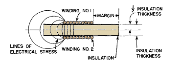
Ordinarily, a winding is separated from the winding under it by wraps of Kraft paper or other insulation. In the coil of Fig. 41 the insulation thickness between winding 1 and winding 2 is shown divided by an imaginary center line. With equal margins in the two windings, the voltage stress is symmetrical about this center line. Margins should be such that there is sufficient creepage distance, in conjunction with one-half the insulation thickness, to withstand one-half the test voltage between these adjacent windings. That is, when full test voltage is applied between the windings, only half of it appears between the first layer of winding 1 and the center line of the insulation between the windings. If the margins are unequal, the sum of the two margins, in conjunction with the total insulation thickness, should be large enough to withstand the full test voltage, in accordance with Fig. 40. Coils may be divided into "part coils" or sections, to reduce insulation stresses, but such coils should be closely integrated with the circuit. For this reason, part coils are discussed in later chapters.
|
||||||||
Home  Transformer Construction, Materials, and Ratings Transformer Construction, Materials, and Ratings  Creepage Distance Creepage Distance |
||||||||
Last Update: 2011-01-24


